
1. Introduction
This instruction manual provides essential information for the safe and efficient use of your Walfront 24VDC 4-20mA Pressure Transducer. Please read this manual thoroughly before installation, operation, or maintenance to ensure proper functionality and to prevent damage or injury. This device is designed for precise pressure measurement in various industrial applications, converting pressure into a standard 4-20mA electrical signal.
2. Safety Information
- Always ensure the power supply is disconnected before installation or maintenance.
- Only qualified personnel should install, operate, and maintain this device.
- Do not exceed the specified operating pressure or temperature ranges.
- Ensure the pressurized medium is non-corrosive to the stainless steel (304) housing.
- Verify all connections are secure and properly sealed to prevent leaks.
- Adhere to all local electrical and safety codes.
3. Product Overview
The Walfront 24VDC 4-20mA Pressure Transducer is a robust and reliable device designed for accurate pressure measurement. It features a stainless steel (304) construction, IP68 protection, and a standard DIN type connection for versatile application.

Figure 1: Walfront 24VDC 4-20mA Pressure Transducer. This image shows the main view of the pressure transducer, highlighting its stainless steel body and black DIN connector.

Figure 2: Pressure Transducer with Dimensions. The image illustrates the overall length of the transducer, approximately 12cm (4.7 inches), providing a clear indication of its physical size.
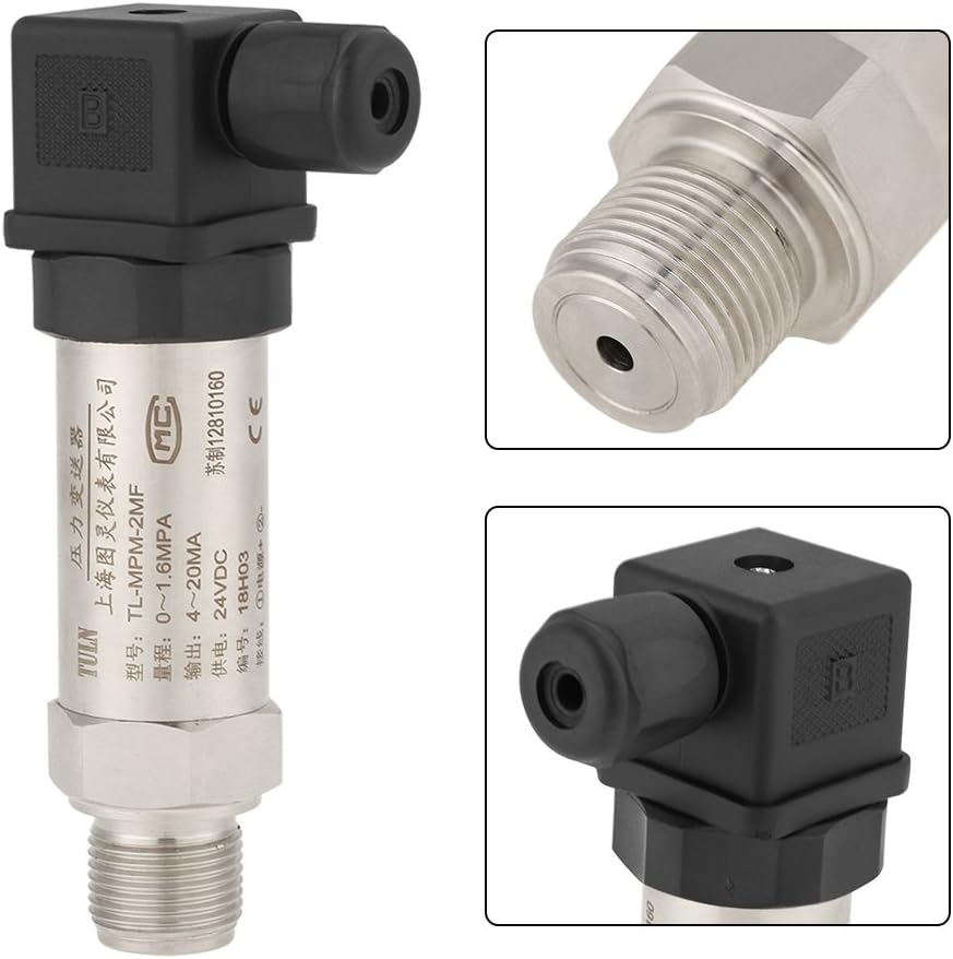
Figure 3: Detailed Views of Pressure Transducer. This composite image provides close-ups of the DIN connector and the ZG 1/4 threaded port, alongside a full view of the device, showing key connection points.
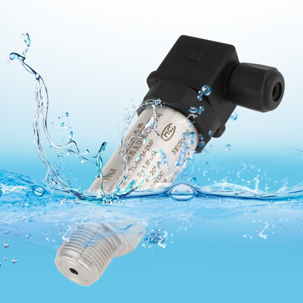
Figure 4: Pressure Transducer in water, illustrating IP68 protection. This image depicts the transducer partially submerged in water with splashes, visually representing its IP68 waterproof and dustproof rating.
4. Specifications
| Parameter | Value |
|---|---|
| Capacity Range | 0-3 bar |
| Integrated Accuracy | 0.1% FS |
| Power Supply | 24VDC |
| Output Signal | 4-20mA |
| Overload Capacity | 25 bar (damaged if exceeded) |
| Operating Temperature Range | -10 ℃ to 100 ℃ |
| Pressurized Medium | Non-corrosive liquid or air |
| Zero Temperature Influence | Typical: 0.02% FS / C; Max: 0.05% FS / C |
| Temperature Drift Sensitivity | Typical: 0.02% FS / C; Max: 0.05% FS / C |
| Shell Material | Stainless steel (304) |
| Connection Type | DIN type |
| Explosion-proof Class | ExiaIICT6 |
| Long-term Stability | Less than 0.2% FS / year |
| Protection Class | IP68 |
| Port Thread | ZG 1/4 |
| Length | 12 cm / 4.72 in |
| Weight | 240 g |
| Manufacturer Reference | Walfrontggmaw2huqv |
| UPC | 715538683556 |
5. Setup
5.1 Mechanical Installation
- Ensure the pressure port is clean and free of debris.
- Apply appropriate thread sealant (e.g., PTFE tape) to the ZG 1/4 port thread.
- Carefully screw the transducer into the pressure source connection point.
- Tighten the transducer securely, but do not overtighten, to prevent damage to the threads or the sensor.
- Ensure the transducer is positioned to avoid physical stress or vibration.
5.2 Electrical Connection
The transducer requires a 24VDC power supply and provides a 4-20mA output signal. Refer to the wiring diagram for correct connections.
- Power Supply: Connect the positive (+) terminal of the 24VDC power supply to the appropriate input terminal on the DIN connector.
- Ground: Connect the negative (-) terminal of the 24VDC power supply to the ground terminal.
- Output Signal: Connect the 4-20mA output signal wire to your control system's analog input.
- Ensure all electrical connections are secure and insulated to prevent short circuits.
6. Operating Instructions
- After mechanical and electrical installation, apply the 24VDC power supply.
- The transducer will immediately begin converting the measured pressure into a 4-20mA output signal.
- Monitor the output signal on your connected control system or display device.
- The 4mA signal corresponds to the minimum pressure (0 bar), and the 20mA signal corresponds to the maximum pressure (3 bar) within its specified range.
- Ensure the operating pressure remains within the 0-3 bar range to maintain accuracy and prevent damage.
7. Maintenance
The Walfront Pressure Transducer is designed for long-term stability and requires minimal maintenance. However, periodic checks are recommended:
- Visual Inspection: Regularly inspect the transducer for any signs of physical damage, corrosion, or loose connections.
- Connection Integrity: Check the mechanical and electrical connections for tightness and proper sealing.
- Cleaning: If necessary, gently clean the exterior of the transducer with a soft, damp cloth. Do not use abrasive cleaners or solvents.
- Calibration Check: For critical applications, periodic calibration checks against a known standard are recommended to ensure continued accuracy.
8. Troubleshooting
| Problem | Possible Cause | Solution |
|---|---|---|
| No output signal (0mA) | No power supply; Incorrect wiring; Damaged transducer | Check 24VDC power supply; Verify wiring connections; Replace transducer if damaged. |
| Output signal stuck at 4mA or 20mA | Pressure outside measurement range; Transducer fault | Ensure pressure is within 0-3 bar; Test transducer with known pressure; Replace if faulty. |
| Inaccurate readings | Incorrect calibration; Sensor drift; External interference | Perform calibration check; Check for strong electromagnetic fields; Ensure stable operating conditions. |
| Leakage at connection point | Improper thread sealant; Loose connection; Damaged threads | Reapply thread sealant; Tighten connection; Inspect threads for damage. |
If troubleshooting steps do not resolve the issue, contact Walfront customer support or a qualified technician.
9. Warranty and Support
This Walfront Pressure Transducer is subject to a return policy of 31 days from the date of purchase. For specific warranty details beyond the return period, please refer to the terms provided by the manufacturer, Walfront, or contact the seller, nineoneeu, directly. Keep your purchase receipt for any warranty claims.
For technical support or further inquiries, please contact Walfront customer service through their official channels or the retailer from whom the product was purchased.
