
1. Introduction
This manual provides essential information for the proper use and handling of the Aexit SD6601 LED Driver IC. This component is designed for surface mounting on Printed Circuit Boards (PCBs) and functions as an LED driver. Please read this manual thoroughly before installation and operation to ensure optimal performance and longevity of the device.
2. Product Overview
The SD6601 is a fixed resistor type LED Driver Integrated Circuit packaged in an SOP-8 format, suitable for Surface Mount Technology (SMT) applications. It is commonly used in various electronic circuits requiring LED driving capabilities.
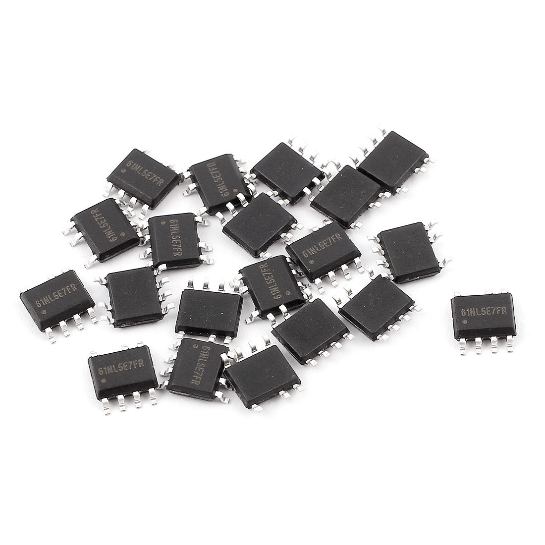
Figure 1: Aexit SD6601 LED Driver IC. This image displays the integrated circuit chip, typically black, with multiple pins extending from its sides, indicating its SOP-8 surface mount package.
Key Features:
- Model: SD6601
- Mounting Type: PCB SMD SMT
- Package: SOP-8
- Dimensions (Approx): 6 x 4 x 1mm (L*W*T)
- Color: Black
- Function: LED Driver IC
3. Specifications
| Parameter | Value |
|---|---|
| Product Name | LED Driver IC |
| Model | SD6601 |
| Mounting Type | PCB SMD SMT |
| Package | SOP-8 |
| Each Size (Approx) | 6 x 4 x 1mm / 0.24" x 0.16" x 0.04" (L*W*T) |
| Color | Black |
| Net Weight (20 Pcs) | 3g |
4. Setup and Installation
The SD6601 is a Surface Mount Device (SMD) and requires specific tools and techniques for proper installation onto a Printed Circuit Board (PCB).
4.1. Required Tools and Materials:
- Soldering Iron with fine tip or Hot Air Rework Station
- Solder paste or fine gauge solder wire
- Flux (no-clean recommended)
- Tweezers or vacuum pick-up tool
- Magnifying glass or microscope
- ESD-safe workstation and wrist strap
4.2. Installation Steps:
- Prepare the PCB: Ensure the PCB pads are clean and free from oxidation. Apply a small amount of solder paste to the pads where the SD6601 will be mounted.
- Component Placement: Carefully align the SD6601 IC with the corresponding pads on the PCB. Use tweezers or a vacuum pick-up tool for precise placement. Ensure the orientation mark on the IC matches the silkscreen on the PCB.
- Soldering:
- Reflow Soldering (Recommended): If using solder paste, carefully heat the PCB and component using a hot air rework station or reflow oven according to the solder paste manufacturer's specifications.
- Manual Soldering: For manual soldering, apply a small amount of flux to the pads. Use a fine-tipped soldering iron to carefully solder each pin to its respective pad. Avoid excessive heat or prolonged contact to prevent damage to the IC.
- Inspection: After soldering, visually inspect all solder joints under magnification to ensure proper connection, no bridges between pins, and no cold solder joints. Clean any flux residue if necessary.
- ESD Precautions: Always handle the IC in an Electrostatic Discharge (ESD) safe environment to prevent damage from static electricity.
5. Operating Principles
The SD6601 functions as an LED driver IC. Its primary role is to regulate the current flowing through one or more LEDs, ensuring stable and efficient illumination. The specific operating parameters (e.g., input voltage, output current, dimming capabilities) depend on the external circuit design in which the SD6601 is integrated.
5.1. Integration into a Circuit:
When integrating the SD6601 into a circuit, refer to the circuit schematic and datasheet (if available from the circuit designer) for proper pin connections, external component values (resistors, capacitors, inductors), and power supply requirements. Incorrect integration can lead to component failure or improper LED operation.
5.2. Power Supply:
Ensure the power supply connected to the circuit containing the SD6601 meets the voltage and current requirements specified by the overall circuit design. Over-voltage or under-voltage conditions can affect the performance and lifespan of the LED driver IC.
5.3. Thermal Management:
Like all integrated circuits, the SD6601 generates heat during operation. Ensure adequate thermal management within the PCB design, especially if driving high-power LEDs, to prevent overheating and maintain optimal performance.
6. Maintenance and Care
The SD6601 LED Driver IC is a robust electronic component designed for long-term reliability. Minimal maintenance is required once properly installed.
6.1. Storage:
- Store unused ICs in their original anti-static packaging in a cool, dry environment.
- Avoid exposure to direct sunlight, high humidity, and extreme temperatures.
6.2. Cleaning:
If cleaning the PCB assembly is necessary, use appropriate electronic cleaning solutions and soft brushes. Avoid harsh chemicals or abrasive materials that could damage the component or solder joints.
6.3. Environmental Conditions:
Operate the circuit containing the SD6601 within its specified environmental conditions (temperature, humidity) to prevent premature failure.
7. Troubleshooting
If the LED driver circuit is not functioning as expected, consider the following common troubleshooting steps:
- No LED Illumination:
- Check power supply voltage and current.
- Verify all solder connections for the SD6601 and associated components.
- Ensure correct polarity of LEDs.
- Inspect for any short circuits or open circuits on the PCB.
- Confirm the SD6601 is correctly oriented.
- Flickering or Unstable LED Output:
- Check for loose connections or intermittent solder joints.
- Verify the stability of the input power supply.
- Ensure external components (e.g., capacitors) are correctly valued and functioning.
- Overheating:
- Ensure adequate ventilation around the PCB.
- Verify that the IC is not being overdriven beyond its specifications.
- Check for short circuits in the LED load.
For complex issues, consult the full circuit schematic and consider professional electronic repair or consultation.
8. Warranty Information
As a component part, the Aexit SD6601 LED Driver IC typically does not come with an individual end-user warranty. The warranty, if any, would be provided by the manufacturer of the final product in which this component is integrated. Please refer to the warranty policy of the complete electronic device for details.
This component is intended for use by experienced electronics professionals or hobbyists. Damage resulting from improper installation, handling, or operation outside of specified parameters is not covered.
9. Support and Contact
For technical support regarding the integration or specific application of the SD6601 LED Driver IC, it is recommended to consult the datasheet provided by the original IC manufacturer or the designer of the circuit in which it is used.
For general inquiries about Aexit products, please refer to the vendor or retailer from whom the product was purchased.
Note: This manual provides general guidance. Specific application details may vary.