1. Introduction
This manual provides essential instructions for the safe and effective operation of the Mustool MT866 Digital True RMS Clamp Meter. The MT866 is a versatile instrument designed for measuring AC/DC voltage, AC/DC current, frequency, temperature, capacitance, resistance, and continuity. It also features a live wire check function and non-contact voltage detection for enhanced safety. Please read this manual thoroughly before using the device.
2. Safety Information
Always adhere to the following safety precautions to prevent personal injury or damage to the meter:
- Do not exceed the maximum input limits for any measurement function.
- Exercise extreme caution when working with live circuits. High voltages can be dangerous.
- Ensure the test leads are in good condition, without any damage to the insulation.
- Do not operate the meter if it appears damaged or if the battery cover is not properly closed.
- Always disconnect the test leads from the circuit before changing the function dial.
- Use the correct function and range for each measurement.
- Keep fingers behind the finger guards on the test probes during measurements.
- Avoid using the meter in wet environments or in the presence of explosive gases or dust.
- The meter is rated for CAT III 600V and CAT II 600V. Do not use it for measurements exceeding these categories.
3. Product Overview
The Mustool MT866 is a compact and feature-rich clamp meter. Familiarize yourself with its components:
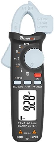
Figure 1: Front View of the Mustool MT866 Clamp Meter. This image displays the main components including the clamp jaw, LCD display, function dial, and control buttons.
3.1. Components
- Clamp Jaw: Used for non-contact AC/DC current measurement.
- Clamp Release Lever: Opens the clamp jaw.
- Non-Contact Voltage (NCV) Sensor: Detects AC voltage without direct contact.
- LCD Display: Shows measurement readings, units, and function indicators.
- Function Dial: Selects the desired measurement mode.
- SEL/ZERO Button: Selects sub-functions or zeros the DC current reading.
- H/💡 Button: Activates Data Hold or backlight.
- V~Alert Button: Activates the V~ alert function for live wire detection.
- Input Terminals (COM, INPUT): For connecting test leads for voltage, resistance, capacitance, frequency, and temperature measurements.
- Back Hook: For convenient hanging of the meter.
3.2. Display Indicators
- AC/DC: Indicates Alternating Current or Direct Current.
- V: Volts (Voltage).
- A: Amperes (Current).
- Ω: Ohms (Resistance).
- F: Farads (Capacitance).
- Hz: Hertz (Frequency).
- °C/°F: Degrees Celsius/Fahrenheit (Temperature).
- LIVE: Live wire detection indicator.
- LOZ: Low impedance voltage measurement mode.
- H: Data Hold activated.
- Battery Symbol: Low battery indicator.
4. Setup
4.1. Battery Installation
The Mustool MT866 requires batteries for operation (not included in the package). To install or replace batteries:
- Ensure the meter is turned off and all test leads are disconnected.
- Locate the battery compartment cover on the back of the meter.
- Unscrew the retaining screw(s) and remove the cover.
- Insert new batteries, observing the correct polarity (+ and -).
- Replace the battery cover and secure it with the screw(s).
4.2. Connecting Test Leads
For most measurements (voltage, resistance, capacitance, etc.), test leads are required.

Figure 2: Mustool MT866 with Test Leads. The black test lead is connected to the COM terminal, and the red test lead is connected to the INPUT terminal.
- Connect the black test lead to the COM (common) input terminal.
- Connect the red test lead to the INPUT terminal.
- Ensure connections are firm before taking any measurements.
5. Operating Instructions
Turn the function dial to the desired measurement mode. Use the SEL/ZERO button to switch between sub-functions (e.g., AC/DC, Resistance/Continuity/Diode).
5.1. AC/DC Voltage Measurement (V)
- Turn the function dial to the V position.
- Use the SEL/ZERO button to select AC (V~) or DC (V=) voltage.
- Connect the test leads in parallel to the circuit or component under test.
- Read the voltage value on the display.
5.2. Low Impedance Voltage (LOZ) Measurement
- Turn the function dial to the LOZ position.
- This mode automatically detects AC or DC voltage with a low input impedance, which can help drain ghost voltages and provide more accurate readings in certain applications.
- Connect the test leads in parallel to the circuit.
5.3. AC/DC Current Measurement (A) - Clamp
- Turn the function dial to the A position.
- Use the SEL/ZERO button to select AC (A~) or DC (A=) current.
- Press the clamp release lever to open the clamp jaw.
- Enclose only one conductor of the circuit within the clamp jaw.
- For DC current, press SEL/ZERO to zero the reading before measurement if necessary.
- Read the current value on the display.
5.4. Resistance (Ω), Continuity, Diode Test
- Turn the function dial to the Ω position.
- Use the SEL/ZERO button to cycle between Resistance, Continuity, and Diode Test modes.
- Resistance: Connect test leads across the component. Ensure the circuit is de-energized.
- Continuity: If resistance is below approximately 30Ω, the buzzer will sound.
- Diode Test: Connect the red lead to the anode and black lead to the cathode. The display shows the forward voltage drop. Reverse the leads to check for open circuit.
5.5. Capacitance (µF) Measurement
- Turn the function dial to the µF position.
- Discharge the capacitor completely before connecting the test leads.
- Connect the test leads across the capacitor terminals.
- Read the capacitance value on the display.
5.6. Frequency (Hz) Measurement
- Frequency can be measured from the jaw (when in AC current mode) or from the input terminals (when in AC voltage mode).
- When in ACV or ACA mode, press the SEL/ZERO button to cycle to the frequency measurement.
- Connect the test leads or clamp the conductor as appropriate for the primary measurement.
5.7. Temperature (°C/°F) Measurement

Figure 3: Mustool MT866 with Temperature Probe. The temperature probe is connected to the input terminals for temperature measurements.
- Turn the function dial to the TEMP position.
- Connect the temperature test probe to the input terminals (red to INPUT, black to COM).
- Place the tip of the temperature probe on or near the object whose temperature is to be measured.
- Read the temperature on the display. Use SEL/ZERO to switch between Celsius and Fahrenheit.
5.8. Live Wire Check (LIVE)
- Turn the function dial to the LIVE position.
- Insert the red test lead into the live wire socket. The display will show "LIVE" and an alarm will sound if a live wire is detected.
5.9. Non-Contact Voltage (V~Alert) Detection
- Press the V~Alert button to activate NCV mode.
- Move the top of the meter (where the NCV sensor is located) close to a conductor or outlet.
- If AC voltage is detected, the meter will beep and the LED indicator will flash, with the intensity increasing as the voltage strength increases.
5.10. µA HVAC Flame Rod Test
- Turn the function dial to the µA position.
- This function is specifically designed for measuring microamperes in HVAC flame rod applications (0-200.0µA).
- Connect the test leads in series with the flame rod circuit.
5.11. Data Hold (H) and Backlight (💡)
- Press the H/💡 button briefly to activate Data Hold, freezing the current reading on the display. Press again to release.
- Press and hold the H/💡 button to turn the backlight on or off.
6. Maintenance
6.1. Cleaning
- Wipe the meter with a damp cloth and mild detergent. Do not use abrasives or solvents.
- Ensure the meter is completely dry before use.
6.2. Battery Replacement
When the battery symbol appears on the display, replace the batteries as described in Section 4.1. Prompt battery replacement ensures accurate readings and proper device function.
6.3. Storage
- If the meter is not used for an extended period, remove the batteries to prevent leakage.
- Store the meter in a cool, dry place, away from direct sunlight and extreme temperatures.
7. Troubleshooting
| Problem | Possible Cause | Solution |
|---|---|---|
| No display or dim display | Low or dead batteries; incorrect battery installation. | Replace batteries; check battery polarity. |
| "OL" or "OVER" displayed | Measurement exceeds the selected range. | Select a higher range or check if the input is too high for the meter. |
| Inaccurate readings | Poor test lead connection; incorrect function/range selected; external interference. | Ensure firm connections; select appropriate function/range; move away from strong electromagnetic fields. |
| No continuity beep | Circuit resistance too high; continuity mode not selected. | Ensure resistance is below 30Ω; press SEL/ZERO to select continuity mode. |
8. Specifications
The following are the general specifications for the Mustool MT866 Digital True RMS Clamp Meter:
- Max. Display: 6000 counts
- AC Current (ACA): 6A/60A/100A (±2.5%+5)
- DC Current (DCA): 6A/60A/100A (±2.5%+5)
- AC Voltage (ACV): 6V/60V/600V (±1%+3)
- DC Voltage (DCV): 6V/60V/600V (±1%+3)
- Low Impedance Voltage (LoZ ACV-DCV Auto Scan): 600.0V / 300kΩ input impedance
- Resistance (OHM): 600Ω/6KΩ/60KΩ/600KΩ/6MΩ/60MΩ (±1%+3)
- Capacitance: 600.0µF/6000µF (±4%+3)
- Frequency (Hz): 60Hz/1000Hz (from jaw or input terminals)
- Temperature: -20~500°C / -4~932°F
- µA HVAC Flame Rod Test: 0~200.0µA
- Continuity Buzzer: Less than 30Ω
- Style: Digital
- Measurement Type: Multimeter
- Safety Rating: CAT III 600V, CAT II 600V
9. Package Contents
The Mustool MT866 package typically includes the following items:
- 1 x Mustool MT866 Digital True RMS Clamp Meter (Batteries are not included)
- 1 x Pair Test Probe (Red and Black)
- 1 x 1M (Length) Temperature Test Probe
- 1 x English User Manual (This document)
10. Warranty and Support
For warranty information, technical support, or service inquiries, please refer to the documentation provided at the time of purchase or contact your retailer. Keep your purchase receipt as proof of purchase.


