
1. Product Overview
The GCSOAR PWM Solar Charge Controller (Model GC1024) is designed for solar power systems, including home solar setups, solar street lights, patio lights, billboards, outdoor camping systems, and marine solar applications. This controller efficiently manages power flow from solar panels to batteries and loads, ensuring system stability and battery longevity.
Key Features:
- Intelligent SOC control chip for stable system operation.
- Overcharge, overdischarge, anti-backflow, and overheating protection.
- Automatic 12V/24V battery type recognition.
- Dual 5V/2A USB outputs for charging mobile devices.
- Series PWM main charging circuit for improved efficiency.
- Enhanced LCD display for intuitive parameter adjustment.
- Constructed with SMT chip production process, high-quality PCB, and industrial-grade chip for durability in various environments.
2. Safety Instructions
- Ensure the battery has sufficient voltage for the controller to recognize its type (12V/24V) before installation.
- Battery cables should be as short as possible to minimize power loss.
- This regulator is ONLY suitable for lead-acid batteries: OPEN, AGM, GEL. It is NOT suitable for lithium batteries or Ni-MH batteries.
- This controller is ONLY suitable for working with photovoltaic solar panels. Do NOT connect to other DC or AC power sources.
- Always connect the battery first, then the load, and finally the solar panel. Disconnect in the reverse order: solar panel, then load, then battery.
3. Product Components and Interface
The GCSOAR PWM Solar Charge Controller features a clear LCD display and intuitive buttons for easy operation. Below is an overview of its main components and connection terminals.

Image: Front view of the GCSOAR PWM Solar Charge Controller, showing the LCD display, control buttons, and dual USB ports.

Image: Detailed view of the LCD display and button functions. The display shows voltage, current, battery status, solar panel status, and load status. Buttons include MENU, UP, DOWN/ON/OFF.
Connection Terminals:

Image: Bottom view of the controller showing the six screw terminals. From left to right: Solar Panel (+/-), Battery (+/-), Load (+/-).
- Solar Terminal: Connects to the solar panel array. Ensure correct polarity (+ and -).
- Battery Terminal: Connects to the battery. Ensure correct polarity (+ and -).
- Load Terminal: Connects to the DC load. Ensure correct polarity (+ and -).
- USB Ports: Dual 5V/2A USB outputs for charging external devices.
4. Setup and Installation
Proper installation is crucial for the safe and efficient operation of your solar charge controller. Follow these steps carefully.
Connection Diagram:

Image: A wiring diagram illustrating the connection of the solar panel, battery, and DC/AC loads to the solar charge controller. It shows the correct sequence of connections.
Installation Steps:
- Connect the Battery: Connect the battery to the controller's battery terminals (+ to + and - to -). Ensure a secure connection. The LCD display will illuminate, showing battery voltage.
- Connect the Load: Connect the DC load to the controller's load terminals (+ to + and - to -).
- Connect the Solar Panel: Connect the solar panel to the controller's solar panel terminals (+ to + and - to -).
Important: Always connect the battery first, then the load, and finally the solar panel. Disconnect in the reverse order: solar panel, then load, then battery.
Installation Video:
Video: A demonstration of connecting the GCSOAR PWM Solar Charge Controller to a battery, load, and solar panel, including an overview of the display and settings.
5. Operating Instructions
The controller's LCD display provides real-time information and allows for parameter adjustments.
LCD Display Navigation:
Press the 'MENU' button to cycle through different display interfaces, showing battery voltage, solar panel current, load current, temperature, and accumulated power generation/consumption.
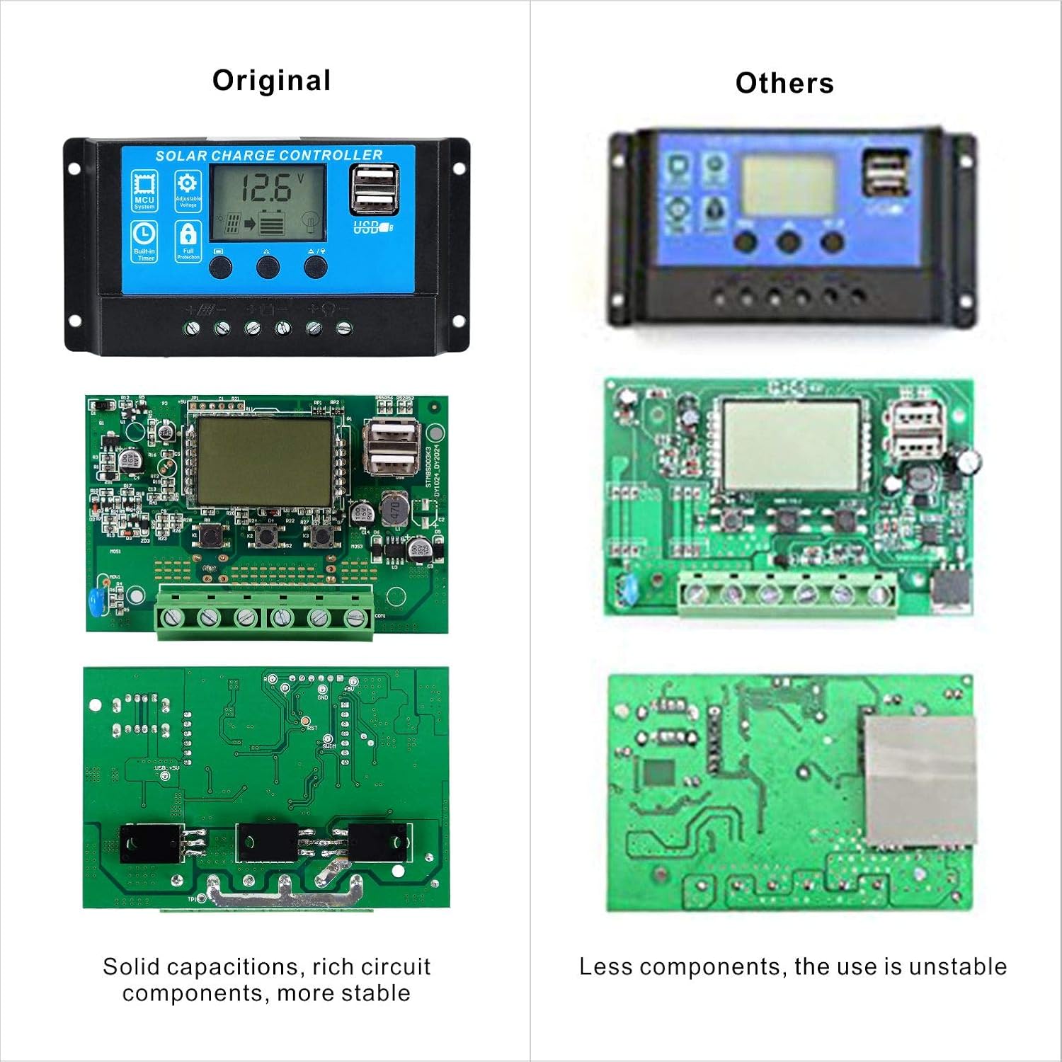
Image: Examples of the LCD display showing different parameters such as battery voltage, charging current, load status, and timer settings.
Parameter Settings:
To enter the setting mode, press and hold the 'MENU' button for 5 seconds. Use the 'UP' and 'DOWN/ON/OFF' buttons to adjust values. Press 'MENU' again to confirm and move to the next parameter. If no operation is performed for 5 seconds, the controller will automatically save settings and exit.
- Battery Type Setting: In the battery voltage interface, press and hold the 'SET' button for 5 seconds to enter battery type setting. Use 'MENU' to select between Sealed (Default), Gel, and Flooded. Wait 5 seconds or press 'SET' to confirm.
- Load Mode Setting (Timer): In the load mode interface, press and hold the 'SET' button for 5 seconds until the number begins flashing. Use 'MENU' to set the parameter (e.g., 24H for 24-hour load, 0H for dusk-to-dawn, or timed settings). Press 'SET' to confirm.
- Load ON/OFF: From the main display, press the 'DOWN/ON/OFF' button to manually turn the load on or off.
USB Charging:
The dual USB ports provide 5V/2A output for charging mobile phones, tablets, and other compatible devices. Simply connect your device to one of the USB ports.
6. Maintenance
Regular maintenance ensures optimal performance and longevity of your solar charge controller.
- Keep the controller in a cool, dry, and well-ventilated area to prevent overheating.
- Periodically check all wire connections for tightness and corrosion.
- Clean the controller's exterior with a dry cloth. Avoid using liquids or abrasive cleaners.
- Monitor the LCD display for any error codes or unusual readings.
7. Troubleshooting
If you encounter issues with your GCSOAR PWM Solar Charge Controller, refer to the following common problems and solutions:
| Problem | Possible Cause | Solution |
|---|---|---|
| LCD display not turning on | Battery not connected or low voltage | Check battery connections and ensure battery voltage is above minimum operating level. |
| No charging from solar panel | Solar panel not connected, insufficient sunlight, or reverse polarity | Check solar panel connections and polarity. Ensure adequate sunlight. |
| Load not working | Load not connected, load current too high, or load output disabled | Check load connections and ensure load current is within specifications. Press 'DOWN/ON/OFF' button to enable load output. |
| Overcharge/Overdischarge protection active | Battery voltage exceeded limits | The controller automatically protects the battery. Ensure correct battery type setting. |
8. Specifications
Detailed technical specifications for the GCSOAR PWM Solar Charge Controller (GC1024).
| Feature | Specification |
|---|---|
| Battery Voltage | 12V/24V Auto |
| Charge/Discharge Current | 10A |
| Max Solar Input Voltage | <50V |
| Max Solar Input Power (12V) | 150W |
| Max Solar Input Power (24V) | 300W |
| USB Output | Dual 5V/2A |
| Operating Temperature | -31°F to 140°F (-35°C to 60°C) |
| Dimensions | 5.31 x 2.68 x 1.26 inches |
| Item Weight | 6.4 ounces |
| Display Type | LCD |
| Compatible Battery Types | OPEN, AGM, GEL (Lead-acid only) |
9. Warranty and Support
GCSOAR is committed to providing quality products and customer satisfaction. For any questions regarding this product, please refer to the Customer Questions & Answers section on the product page or contact GCSOAR customer support.
Our service team in Chicago, Illinois, provides technical support and free solar system design assistance.