
1. Product Overview
This manual provides detailed instructions for the installation and proper use of the ZXTDR Brushless Motor Controller Wiring Harness. This wiring loom is designed for electric mini go-karts, ATVs, and quad bikes, facilitating the connection between a brushless motor and its controller.
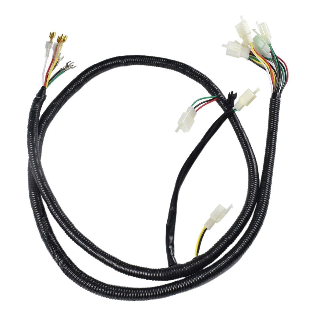
Image 1.1: The complete ZXTDR Brushless Motor Controller Wiring Harness, showing the main loom and various connectors. This harness is essential for connecting brushless motors to their controllers in electric mini go-karts, ATVs, and quad bikes.
2. Safety Information
Before proceeding with installation, please read and understand all safety warnings. Improper installation or use can result in electric shock, damage to equipment, or personal injury.
- Always disconnect power from the vehicle's battery before installing or servicing electrical components.
- Ensure all connections are secure and properly insulated to prevent short circuits.
- Consult a qualified technician if you are unsure about any part of the installation process.
- Wear appropriate personal protective equipment (PPE), such as safety glasses and gloves.
3. Package Contents
Verify that all components are present before beginning installation:
- 1x ZXTDR Brushless Motor Controller Wiring Harness
4. Setup and Installation
This section outlines the general steps for installing the wiring harness. Specific connection points may vary depending on your vehicle and motor controller model. Refer to your vehicle's and motor controller's manuals for detailed wiring diagrams.
4.1 Identify Connectors
Familiarize yourself with the various connectors on the harness. The harness includes multiple types of connectors for different functions, such as power, motor phases, hall sensors, throttle, brake, and ignition.

Image 4.1.1: A close-up view of several white multi-pin connectors on the wiring harness. These connectors are typically used for signal wires, such as throttle input, brake signals, and hall sensor connections from the motor.

Image 4.1.2: A detailed view showing both a white multi-pin connector and a black two-pin connector. These different connector types ensure correct pairing with corresponding components on the motor controller and vehicle.

Image 4.1.3: A close-up of the spade and ring terminals at one end of the wiring harness. These terminals are typically used for power connections, such as battery input or motor phase wires, requiring secure fastening.
4.2 Connection Procedure
- Power Disconnection: Ensure the vehicle's battery is disconnected before starting any wiring work.
- Motor Phase Wires: Connect the three main motor phase wires (typically thicker wires) from the harness to the corresponding phase terminals on your brushless motor controller. Ensure correct color matching if applicable, or follow the controller's instructions for phase identification.
- Hall Sensor Wires: Connect the smaller hall sensor wires (usually five wires: +5V, GND, and three signal wires) from the harness to the hall sensor input on your motor controller.
- Battery Power: Connect the main power input wires from the harness to the vehicle's battery (positive to positive, negative to negative). Use appropriate fuses as recommended by your motor controller manufacturer.
- Throttle Connection: Connect the throttle input wires from the harness to your throttle assembly.
- Brake/Ignition/Other Signals: Connect any remaining signal wires for brakes, ignition, speedometers, or other accessories as per your vehicle and controller's specifications.
- Secure Connections: Double-check all connections for tightness and proper insulation. Use zip ties or electrical tape to secure the harness and prevent chafing or accidental disconnection.
- Power Reconnection: Once all connections are verified, reconnect the vehicle's battery.
5. Operating Instructions
The wiring harness itself does not have operational controls. Its function is to provide reliable electrical connections. Proper operation of your electric vehicle depends on the correct installation of this harness and the functionality of your motor, controller, and other components.
- After installation, perform a functional test of the vehicle in a safe, controlled environment.
- Verify that the motor responds correctly to throttle input and that all safety features (e.g., brake cut-off) are functioning.
- Monitor for any unusual smells, sounds, or excessive heat during initial operation.
6. Maintenance
The ZXTDR Brushless Motor Controller Wiring Harness is designed for durability and requires minimal maintenance. Regular inspection is recommended to ensure continued performance and safety.
- Visual Inspection: Periodically inspect the entire harness for signs of wear, fraying, cuts, or damage to the insulation.
- Connection Check: Ensure all connectors remain securely seated and free from corrosion. Clean any dirty or corroded terminals with an appropriate electrical contact cleaner.
- Cable Routing: Verify that the harness is properly routed and secured, away from moving parts, sharp edges, or heat sources.
- Cleaning: If necessary, gently clean the harness with a damp cloth. Avoid using harsh chemicals or solvents.
7. Troubleshooting
If you encounter issues after installing the wiring harness, consider the following troubleshooting steps:
| Problem | Possible Cause | Solution |
|---|---|---|
| Motor not responding / No power |
|
|
| Motor runs erratically / Jerky movement |
|
|
| Throttle not working |
|
|
If problems persist after troubleshooting, contact ZXTDR customer support or a qualified technician.
8. Specifications
| Feature | Detail |
|---|---|
| Product Name | Brushless Motor Controller Wire Wiring Harness Loom |
| Brand | ZXTDR |
| Model | ZXTDR Brushless Motor Controller Wiring Harness |
| Material | Loom (Wiring Harness) |
| Cable Length | Approximately 1450mm (1.45 meters) |
| Compatibility | Electric Mini Go Kart, ATV, Quad Bikes (with compatible brushless motor and controller) |
| ASIN | B07BQKWTP7 |
| UPC | 190835715917 |
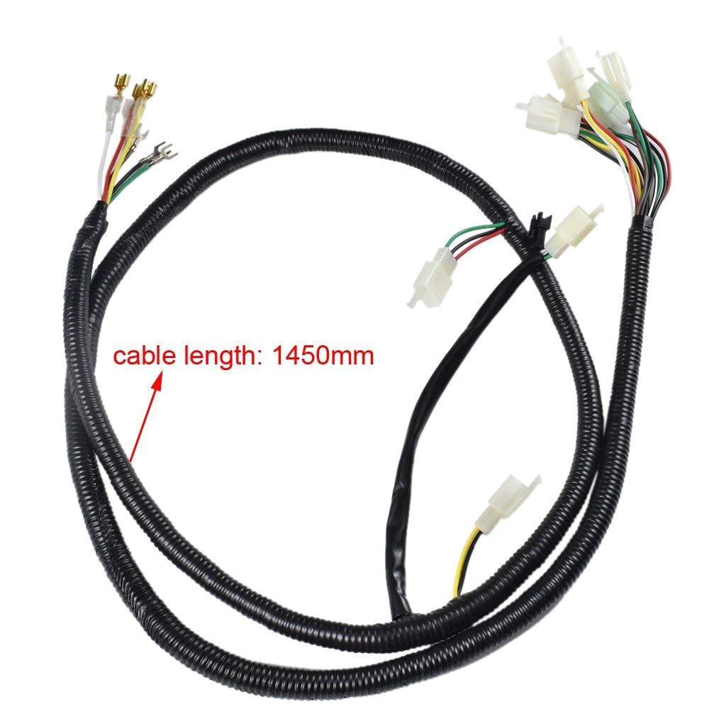
Image 8.1: The ZXTDR wiring harness with an annotation indicating a cable length of 1450mm. This length provides flexibility for installation in various vehicle types.
9. Warranty and Support
ZXTDR products are manufactured to high standards. For warranty information, returns, or technical assistance, please refer to the seller's policy on the platform where the product was purchased or visit the official ZXTDR store.
Manufacturer: ZXTDR
Date First Available: March 26, 2018
For further inquiries, please contact ZXTDR customer service.