
1. Introduction
This manual provides detailed instructions for the safe and effective use of the MeterTo Victor 3010 Analog Multimeter. This device is designed for measuring DC voltage, AC voltage, DC current, resistance, dBm, and performing continuity and triode tests. Please read this manual thoroughly before operating the multimeter to ensure proper function and to prevent potential hazards.
2. Safety Information
WARNING: To avoid electric shock or personal injury, and to prevent damage to the meter or to the equipment under test, follow these safety rules:
- Always ensure the test leads are in good condition, without cracks or breaks in the insulation.
- Do not apply more than the rated voltage, as marked on the meter, between the terminals or between any terminal and ground.
- Use caution when working with voltages above 30V AC RMS, 42V peak, or 60V DC. Such voltages pose a shock hazard.
- Always disconnect the test leads from the circuit before changing functions or ranges.
- Do not use the meter if it appears damaged or if it is not operating properly.
- Observe all local and national safety codes.
3. Product Overview
The Victor 3010 is a manual range analog multimeter featuring a clear analog display and a rotary selector switch for various measurement functions. It is designed for general electrical testing applications.
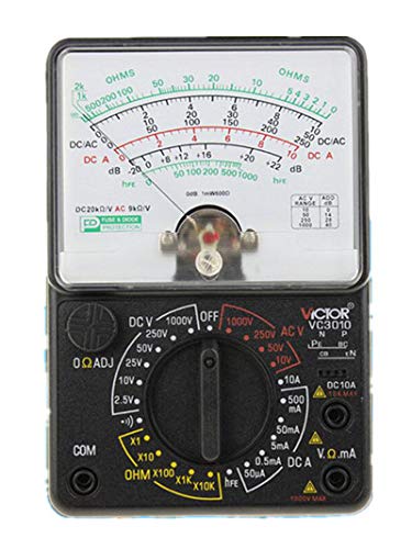
Figure 1: Front view of the MeterTo Victor 3010 Analog Multimeter. The image shows the main analog display, the central rotary selector switch, input jacks for test leads, and various measurement scales printed on the meter face.
Key Components:
- Analog Display: Shows measurement readings via a needle on a calibrated scale.
- Rotary Selector Switch: Used to select the desired measurement function (e.g., DCV, ACV, DCA, Ω) and range.
- Input Jacks: Terminals for connecting test leads (typically COM, VΩmA, 10A).
- Zero Adjustment Knob: Used to set the needle to zero for resistance measurements.
4. Setup
4.1. Battery Installation
The Victor 3010 requires R6 (ICE) or UM-3, 1.5V x 2, and a 9V battery for operation. To install or replace batteries:
- Ensure the multimeter is turned off and test leads are disconnected.
- Locate the battery compartment on the back of the unit.
- Open the compartment cover.
- Insert the batteries, observing correct polarity (+ and -).
- Close the battery compartment cover securely.
4.2. Connecting Test Leads
Connect the red test lead to the VΩmA jack and the black test lead to the COM (common) jack for most measurements. For high current measurements (e.g., 10A), connect the red lead to the 10A jack.
5. Operating Instructions
Before taking any measurement, ensure the test leads are correctly connected and the rotary switch is set to the appropriate function and range. Always start with a higher range if the approximate value of the measurement is unknown, then switch to a lower range for better accuracy.
5.1. DC Voltage (DCV) Measurement
- Set the rotary switch to the desired DCV range (e.g., 2.5V, 10V, 25V, 50V, 250V, 1000V).
- Connect the test leads in parallel to the circuit or component to be measured.
- Read the voltage value from the DCV scale on the analog display.
5.2. AC Voltage (ACV) Measurement
- Set the rotary switch to the desired ACV range (e.g., 10V, 50V, 250V, 1000V).
- Connect the test leads in parallel to the AC circuit or component.
- Read the voltage value from the ACV scale on the analog display.
5.3. DC Current (DCA) Measurement
CAUTION: Never connect the multimeter in parallel when measuring current. Always connect in series with the load.
- Set the rotary switch to the desired DCA range (e.g., 50uA, 0.5mA, 5mA, 50mA, 500mA, 10A).
- Break the circuit and connect the multimeter in series with the load.
- Read the current value from the DCA scale.
5.4. Resistance (Ω) Measurement
- Set the rotary switch to the desired Ω range (e.g., ×1Ω, ×10Ω, ×100Ω, ×1KΩ, ×10kΩ).
- Before measuring, short the test leads together and adjust the Zero Adjustment Knob until the needle points to '0' on the Ω scale.
- Connect the test leads across the component to be measured (ensure the component is de-energized).
- Read the resistance value from the Ω scale and multiply by the selected range multiplier.
5.5. dBm Measurement
- Set the rotary switch to the dBm function.
- Connect the test leads to the circuit.
- Read the dBm value from the corresponding scale.
5.6. Continuity Test
- Set the rotary switch to the continuity test function (often shared with a low resistance range).
- Connect the test leads across the circuit or component.
- A low resistance reading (or an audible tone if equipped) indicates continuity.
5.7. Triode Test
Refer to the specific markings on the multimeter's dial for triode testing. This typically involves inserting the transistor leads into designated sockets on the meter and selecting the appropriate function.
6. Maintenance
6.1. Cleaning
Wipe the meter with a damp cloth and mild detergent. Do not use abrasives or solvents. Ensure the meter is dry before use.
6.2. Battery Replacement
Replace batteries when the meter's readings become unstable or inaccurate, or if the low battery indicator (if present) illuminates. Refer to Section 4.1 for battery installation instructions.
6.3. Storage
If the meter is not used for an extended period, remove the batteries to prevent leakage. Store the meter in a cool, dry place away from direct sunlight.
7. Troubleshooting
- No reading or unstable reading: Check battery condition and replacement if necessary. Ensure test leads are properly connected and not damaged. Verify the rotary switch is set to the correct function and range.
- Incorrect resistance reading: Perform zero adjustment for resistance (Section 5.4). Ensure the component is de-energized.
- Meter does not turn on: Check battery installation and ensure batteries are charged.
If the issue persists after performing these checks, contact customer support.
8. Specifications
| Parameter | Value |
|---|---|
| DC Voltage (DCV) | 2.5V / 10V / 25V / 50V / 250V / 1000V (±3%) |
| AC Voltage (ACV) | 10V / 50V / 250V / 1000V (±4%) |
| DC Current (DCA) | 50uA / 0.5mA / 5mA / 50mA / 500mA / 10A (±3%) |
| Resistance (Ω) | ×1Ω / ×10Ω / ×100Ω / ×1KΩ / ×10kΩ (±3%) |
| dBm | -10dB ~ +22dB (10VAC ~ +62 dB) |
| Triode Test | Yes |
| Continuity Test | Yes |
| Input Impedance | (9-20)kΩ |
| Operation Mode | Manual range |
| Power | R6(ICE) or UM-3, 1.5V × 2, 9V |
| Item Weight | 3.31 Pounds |
9. Warranty and Support
This MeterTo Victor 3010 Analog Multimeter is covered by a standard manufacturer's warranty against defects in materials and workmanship. For specific warranty terms and conditions, please refer to the warranty card included with your product or contact MeterTo customer support.
For technical assistance, troubleshooting, or service inquiries, please contact MeterTo customer support through their official website or the contact information provided with your purchase.