
1. Introduction
This manual provides detailed instructions for the safe and effective operation, maintenance, and troubleshooting of the MeterTo Victor 60D+ Digital Insulation Tester. This device is designed for measuring insulation resistance and AC voltage, offering high accuracy and reliability for professional use.
2. Safety Information
WARNING: To avoid electric shock or personal injury, please read and understand all safety information before using this instrument. Improper use can result in severe injury or death.
- Always inspect the tester and test leads for damage before use. Do not use if damaged.
- Ensure the test leads are properly connected to the correct terminals for the measurement being performed.
- Do not apply voltage to the tester that exceeds the maximum rated voltage.
- Do not operate the tester in wet environments or with wet hands.
- Always discharge the circuit under test after insulation resistance measurements, as high voltage can remain stored.
- Replace batteries promptly when the low battery indicator appears to ensure accurate readings.
- Servicing should only be performed by qualified personnel.
3. Product Overview
The Victor 60D+ is a robust digital insulation tester featuring a clear LCD display and intuitive controls. It is housed in a durable casing designed for field use.
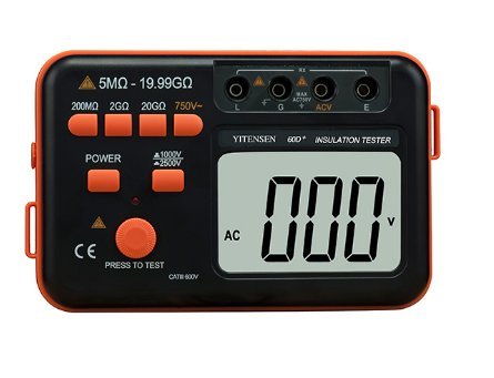
Figure 3.1: Front view of the Victor 60D+ Digital Insulation Tester. This image displays the main LCD screen, the various function buttons for range selection (200MΩ, 2GΩ, 20GΩ, 750V~), power, and test activation, along with the input terminals labeled L, E, ACV, and G.
Key components include:
- LCD Display: Shows measurement readings, unit symbols, and battery status.
- Function Buttons: For selecting measurement ranges (200MΩ, 2GΩ, 20GΩ, 750V~) and test voltages (1000V, 2500V).
- POWER Button: To turn the device on or off.
- PRESS TO TEST Button: Initiates an insulation resistance measurement.
- Input Terminals: L (Line), E (Earth), ACV (AC Voltage), G (Guard/Ground).
- DC 12V Input: For external power supply (if applicable, though battery powered is specified).

Figure 3.2: Angled view of the Victor 60D+ Digital Insulation Tester, showing the device partially removed from its protective orange and black casing. This view highlights the robust design and the side profile of the unit.
4. Setup
4.1 Battery Installation
The Victor 60D+ requires eight (8) LR6 (1.5V) AA batteries for operation. Ensure the device is powered off before installing or replacing batteries.
- Locate the battery compartment cover on the back of the unit.
- Open the battery compartment by sliding or unscrewing the cover.
- Insert eight LR6 (1.5V) AA batteries, observing the correct polarity (+/-) as indicated inside the compartment.
- Close the battery compartment cover securely.
A low battery indicator will appear on the display when batteries need replacement.
5. Operating Instructions
5.1 Powering On/Off
Press the POWER button to turn the tester on. Press it again to turn the tester off. The device features an auto power-off function to conserve battery life after a period of inactivity.
5.2 Insulation Resistance Measurement
Before performing any insulation resistance measurement, ensure the circuit under test is completely de-energized and safely discharged.
- Connect the test leads: Connect the Line (L) test lead to the circuit point to be tested and the Earth (E) test lead to the ground or reference point.
- Select the desired test voltage: Use the buttons to select either 1000V or 2500V.
- Select the appropriate resistance range: Choose from 200MΩ, 2GΩ, or 20GΩ based on the expected resistance value. Start with a higher range if unsure.
- Press and hold the PRESS TO TEST button. The tester will apply the selected voltage and display the insulation resistance value. A red indicator light will illuminate during the test.
- Release the PRESS TO TEST button to stop the measurement.
- After measurement, ensure the circuit is discharged before disconnecting the test leads.
Note: The median resistance for the 1000V range is 6-199.9MΩ for 200MΩ, 0.06-1.999GΩ for 2GΩ, and 0.6-19.99GΩ for 20GΩ. For the 2500V range, it is 5-199.9MΩ for 200MΩ, 0.05-1.999GΩ for 2GΩ, and 0.5-19.99GΩ for 20GΩ.
5.3 AC Voltage Measurement
The Victor 60D+ can also measure AC voltage up to 750V.
- Connect the test leads: Connect one test lead to the ACV terminal and the other to the G (Ground) terminal.
- Connect the test leads across the AC voltage source to be measured.
- The display will show the AC voltage reading.
Note: The accuracy for AC750V measurement is ±(1% +6bit).
6. Maintenance
6.1 Cleaning
Wipe the case with a damp cloth and mild detergent. Do not use abrasives or solvents. Ensure the device is dry before use.
6.2 Battery Replacement
Refer to Section 4.1 for detailed battery installation and replacement instructions. Always replace all eight batteries simultaneously with new ones of the same type (LR6 1.5V AA).
6.3 Storage
If the tester is not used for an extended period, remove the batteries to prevent leakage and damage. Store the device in a cool, dry place, away from direct sunlight and extreme temperatures.
7. Troubleshooting
| Problem | Possible Cause | Solution |
|---|---|---|
| Tester does not power on. | Dead or incorrectly installed batteries. | Check battery polarity and replace all batteries. |
| "1" displayed (Over Range). | Measurement exceeds selected range or maximum capacity. | Select a higher measurement range or verify the circuit is within the tester's limits. |
| Low Battery Indicator. | Batteries are low. | Replace all eight LR6 (1.5V) AA batteries. |
| Inaccurate readings. | Poor test lead connection, low batteries, or environmental factors. | Ensure secure connections, replace batteries, and operate within specified temperature/humidity ranges. |
8. Specifications
| Parameter | Value |
|---|---|
| Measuring Voltage | 1000V / 2500V (±10%) |
| Median Resistance | <4mA |
| Median Voltage | 1000V |
| Insulation Resistance (1000V) |
|
| Insulation Resistance (2500V) |
|
| AC Voltage Measurement | AC750V (±(1% +6bit)) |
| Jack Position | Insulation resistance: L, E; AC750V: ACV, G |
| Overload Indication | Yes |
| Auto Power Off | Yes |
| Max. Display | 1999 |
| Product Dimension | 175 × 110 × 70 mm |
| Product Net Weight | Approx. 720g (including battery) |
| Power Source | 8 x LR6 (1.5V) AA batteries |
| Operating Temperature | 0℃ ~ 40℃ |
| Relative Humidity | 30%RH ~ 85%RH |
| Low Battery Indication | Yes |
| Alarm Function | Red indicator light illuminates |
| Unit Symbol Display | Yes |
| Over Range Display | "1" |