
1. Introduction
The EPEVER LS1012EU is a highly efficient PWM solar charge controller designed for off-grid solar panel battery charging systems. It features advanced digital techniques, ensuring reliable and cost-effective operation. This controller is equipped with a USB output port for charging electronic devices and provides comprehensive electronic protections to safeguard your system.
Key features include 3-stage intelligent PWM charging (Bulk, Boost/Equalize, Float), support for various battery types (Sealed, Gel, Flooded), intuitive LED indicators for battery status, and temperature compensation.
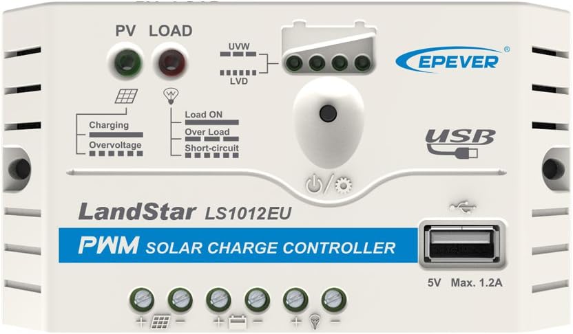
Figure 1: Front view of the EPEVER LS1012EU Solar Charge Controller, showing its compact design and various indicators.
Product Features and Components

Figure 2: Labeled components of the LS1012EU controller, indicating mounting holes, terminals, USB port, button, and LED indicators.
- Mounting Hole (Φ4.5): Used for securing the controller to a surface.
- PV Terminals: Connect to the solar panel array.
- Battery Terminals: Connect to the battery bank.
- Load Terminals: Connect to DC loads.
- USB Output Port: Provides 5V/1.2A power for charging electronic devices.
- Button: Used for setting battery type and load output.
- Battery Status LED Indicator: Displays the battery's charge status.
- Load Status LED Indicator: Shows the status of the connected load (ON/OFF, Overload, Short-circuit).
- Charging Status LED Indicator: Indicates charging activity and overvoltage conditions.
2. Important Safety Information
Please read all instructions in this manual carefully before installation and operation. Failure to follow these instructions may result in damage to the controller, battery, or other components, and may cause personal injury.
- DO NOT disassemble or attempt to repair the controller.
- Install external fuse or breaker as required for safety.
- Always disconnect the solar module and fuses/breakers near the battery before installing or moving the controller.
- Ensure all power connections remain tight to avoid excessive heating from loose connections.
- Only charge batteries that comply with the parameters of this controller.
- Battery connection may be wired to a single battery or a bank of batteries.
- Be aware of the risk of electric shock; the PV array and load can produce high voltages when the controller is operating.
3. Installation and Setup
Follow these steps for proper installation of your EPEVER LS1012EU solar charge controller.
Connection Diagram

Figure 3: Typical connection diagram for the LS1012EU, showing connections to solar panel, battery, and DC load.
Installation Steps
- Prepare Wiring: Ensure all wires are of appropriate gauge (14AWG/2.5mm²) and have proper insulation.
- Connect Battery: Connect the battery to the battery terminals (positive to positive, negative to negative) on the controller. The controller will detect the battery voltage. Ensure the battery is connected first.
- Connect Load: Connect the DC load to the load terminals on the controller.
- Connect Solar Panel: Connect the solar panel to the PV terminals on the controller. Ensure correct polarity.
- Mounting: Secure the controller to a flat, vertical surface using the mounting holes (Φ4.5mm). Ensure adequate ventilation around the controller.
Important: Always connect the battery first, then the solar panel, and finally the load. Disconnect in the reverse order: solar panel, then load, then battery.
4. Operating Instructions
The LS1012EU controller is designed for easy operation with intuitive indicators and simple settings.
LED Indicators
| Indicator | Status | Description |
|---|---|---|
| Charging Status LED (PV) | Green ON | Charging in progress. |
| Green Flashing | Overvoltage protection active. | |
| Load Status LED (LOAD) | Red ON | Load output is ON. |
| Red Flashing (slow) | Overload protection active. | |
| Red Flashing (fast) | Short-circuit protection active. | |
| Battery Status LED (U/V/W, LVD) | Green | Battery voltage is high (U). |
| Orange | Battery voltage is medium (V). | |
| Red | Battery voltage is low (W). | |
| Red Flashing | Low Voltage Disconnect (LVD) active. |
Setting Battery Type and Load Output
The single button on the controller allows for easy configuration:
- Battery Type Setting: Press and hold the button for 5 seconds to enter battery type setting mode. The Battery Status LED will flash. Press the button briefly to cycle through battery types:
- Green: Sealed battery
- Orange: Gel battery
- Red: Flooded battery
- Load Output Control: Briefly press the button (less than 3 seconds) to manually turn the load output ON or OFF. The Load Status LED will indicate the current state.
USB Output
The integrated USB port provides a 5V/1.2A output, suitable for charging various electronic devices such as mobile phones or small USB-powered gadgets.
5. Maintenance
Regular maintenance ensures the longevity and optimal performance of your solar charge controller.
- Check Connections: Periodically inspect all wiring connections to ensure they are tight and free from corrosion. Loose connections can cause excessive heat and damage.
- Clean Controller: Keep the controller clean and free from dust and debris. Use a dry cloth to wipe the surface. Do not use liquid cleaners.
- Inspect for Damage: Visually inspect the controller for any signs of physical damage, such as cracks, frayed wires, or discolored components.
- Ventilation: Ensure the installation location provides adequate airflow around the controller to prevent overheating.
- Battery Health: Monitor your battery's health and electrolyte levels (for flooded batteries) as per the battery manufacturer's recommendations.
6. Troubleshooting
This section outlines common issues and their potential solutions.
| Problem | Possible Cause | Solution |
|---|---|---|
| No LED indicators light up. | Battery not connected or reverse polarity; battery voltage too low. | Check battery connections and polarity. Ensure battery voltage is above 8V. |
| Battery not charging (PV LED OFF). | No solar input; PV reverse polarity; PV open circuit voltage too low. | Check solar panel connections and polarity. Ensure sufficient sunlight and PV voltage. |
| Load not working (Load LED OFF). | Load output turned OFF; battery low voltage disconnect (LVD); overload/short-circuit protection. | Briefly press button to turn load ON. Charge battery. Reduce load or check for short-circuit. |
| Load LED flashing rapidly. | Load short-circuit protection active. | Disconnect load, check for short-circuit in wiring or device, then reconnect. |
| Load LED flashing slowly. | Load overload protection active. | Reduce the total power consumption of connected loads. |
| PV LED flashing. | PV overvoltage protection active. | Ensure PV open circuit voltage does not exceed 30V. |
If the problem persists after attempting these solutions, please contact customer support.
7. Technical Specifications
Detailed technical specifications for the EPEVER LS1012EU Solar Charge Controller.

Figure 4: Comprehensive technical data for LS series controllers, including LS1012EU.
| Parameter | Value (LS1012EU) |
|---|---|
| Nominal System Voltage | 12VDC |
| Rated Charge Current | 10A |
| Rated Discharge Current | 10A |
| Battery Input Voltage Range | 8V ~ 16V |
| Max. PV Open Circuit Voltage | 30V |
| Self-consumption | ≤3mA (12V) |
| Charge Circuit Voltage Drop | ≤0.12V |
| Discharge Circuit Voltage Drop | ≤0.10V |
| Temperature Compensation Coefficient | -5mV/°C/2V |
| Working Environment Temperature | -35°C ~ +55°C |
| Humidity | ≤95% N.C. |
| Enclosure | IP20 |
| Grounding | Common Positive |
| Overall Dimension | 120.3 x 67.2 x 21.8 mm |
| Mounting Dimension | 111.5 mm |
| Mounting Hole Size | Φ4.5 mm |
| Terminals | 14AWG / 2.5mm² |
| Net Weight | 0.103 kg |
| USB Output | 5VDC/1.2A |
8. Warranty and Support
EPEVER products are supported by authorized sales agents to ensure customer satisfaction.
GolandCentury, an official authorized sales agent for EPEVER, offers the latest versions of controllers and accessories. They have established warehouses and service centers in key regions including Chicago (USA), Munich (Germany), Toronto (Canada), and Melbourne (Australia).
For technical assistance or inquiries, please contact their technical support team. They provide free technical support to assist with any product-related questions or issues.
For specific warranty terms and conditions, please refer to the warranty card included with your product or contact your point of purchase.


