
EPEVER VS4524AU
EPEVER Solar Charge Controller 45A VS4524AU User Manual
Brand: EPEVER | Model: VS4524AU
1. Introduction and Features
The EPEVER VS-AU series solar charge controller is a Pulse Width Modulation (PWM) charge controller equipped with a built-in LCD display. It incorporates advanced digital techniques to efficiently manage solar panel battery charging. Its versatile load control modes make it suitable for various applications, including solar home systems, traffic signals, solar street lights, and solar garden lamps.
Key Features:
- 3-Stage intelligent PWM charging: Bulk, Boost/Equalize, Float.
- Supports three charging options: Sealed, Gel, and Flooded batteries.
- LCD display dynamically shows device operating data and working conditions.
- Dual USB ports (5V/2.4A output) for charging electronic equipment.
- User-friendly button settings for comfortable and convenient operation.
- Multiple load control modes.
- Energy statistics function.
- Battery temperature compensation function.
- Extensive Electronic protection.
2. Safety Information
Please read all instructions and warnings carefully before installation and operation. Keep this manual for future reference. Always ensure proper polarity and connections to prevent damage to the controller, battery, or other connected devices. Disconnect all power sources before performing any maintenance or wiring changes.
Electronic Protections:
- PV reverse polarity protection
- Battery over voltage protection
- Battery over discharge protection
- Battery reverse polarity protection
- Battery overheating protection
- Load overload protection
- Load short circuit protection
- Controller overheating protection
3. Product Components and Overview
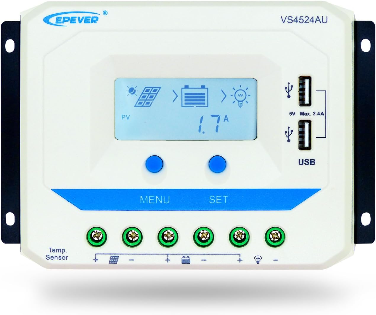
Figure 3.1: Front view of the EPEVER VS4524AU Solar Charge Controller, showing the LCD display, control buttons, and USB ports.

Figure 3.2: Detailed view of the controller's front panel with labels for the LCD display, Menu button, Set button, USB output ports (5VDC/2.4A), RTS port, PV terminals, Battery terminals, and Load terminals.

Figure 3.3: Rear view of the EPEVER VS4524AU Solar Charge Controller, highlighting the heat sink for efficient heat dissipation.
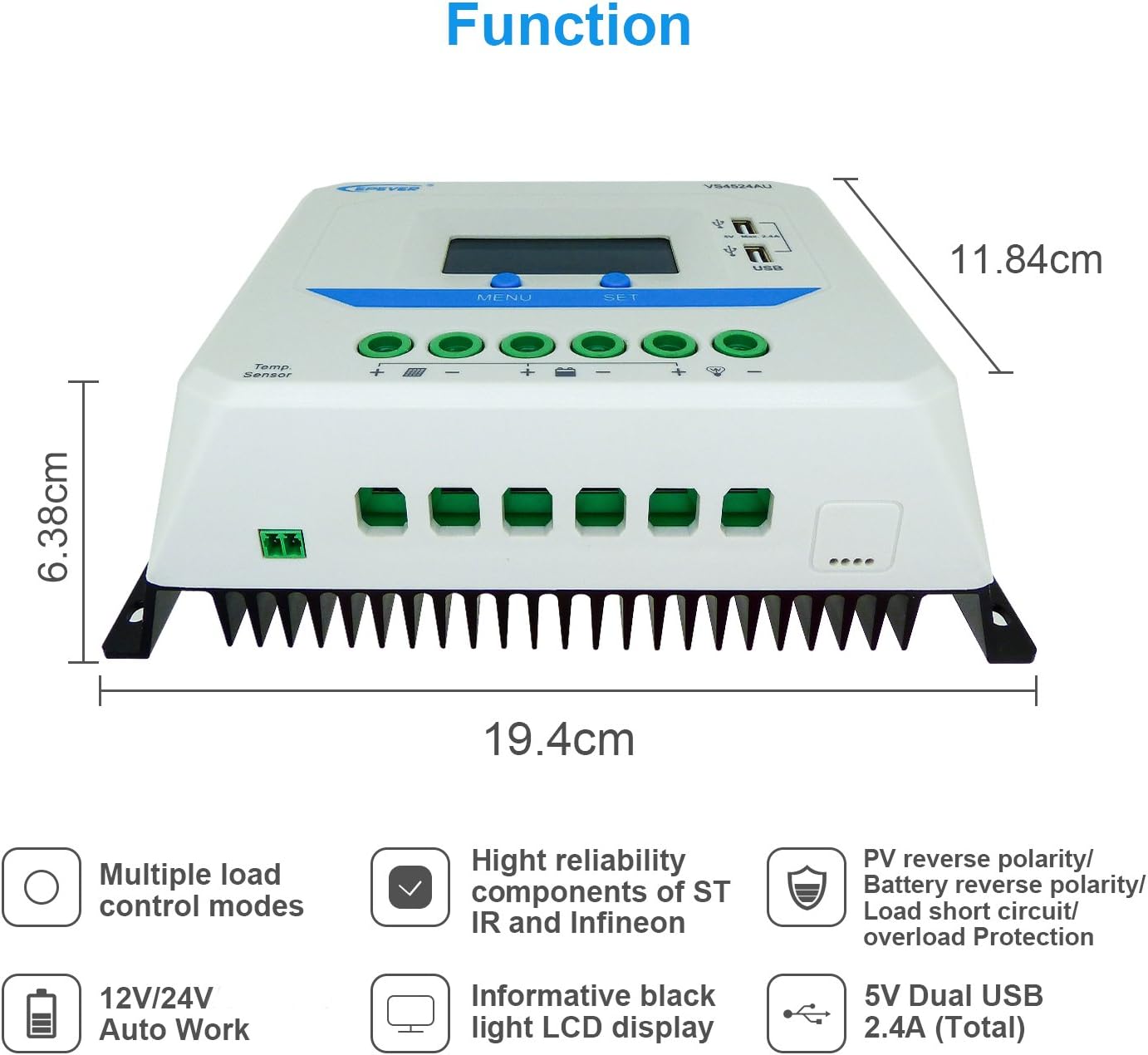
Figure 3.4: Dimensions of the controller (19.4cm x 11.84cm x 6.38cm) and a summary of its functions including multiple load control modes, high reliability components, informative black light LCD display, 12V/24V auto work, 5V dual USB 2.4A (Total) output, and various protections.
4. Installation
Important: Always connect the battery first. Do not use an electric screwdriver for connections. Please read the complete installation instructions to familiarize yourself with the steps before proceeding.
Connection Diagram:

Figure 4.1: Wiring diagram showing the connection order: 1. Battery, 2. Load, 3. Solar panel (PV array). Also illustrates optional inverter and USB charging for devices like phones and pads.
Connecting Steps:
- Connect the Battery: Connect the battery to the controller's battery terminals. Ensure correct polarity (positive to positive, negative to negative). The controller will power on and display battery voltage.
- Connect the Load: Connect the load to the controller's load terminals. Ensure correct polarity.
- Connect the Solar Panel (PV Array): Connect the solar panel to the controller's PV terminals. Ensure correct polarity.
Disconnecting Steps (Reverse Order):
- Disconnect the Load.
- Disconnect the Solar Panel (PV array).
- Disconnect the Battery.
Installation and Operation Video Guide:
This video provides a visual guide to unboxing, connecting the battery, load, and solar panel, and navigating the controller's interface. It demonstrates how to check battery and load parameters, and how to set load modes.
5. Operating Instructions
LCD Display and Button Functions:
The controller features an LCD display that shows real-time operating data. The "MENU" and "SET" buttons are used to navigate and configure settings.
- MENU Button: Used to browse through different display interfaces (e.g., PV parameters, Battery parameters, Load parameters).
- SET Button: Used to confirm settings or to enter setting modes by holding for 5 seconds.
- Backlight Display: The LCD has a backlight for visibility in low light conditions.
- USB Output: Provides 5V, Max 2.4A output for charging external devices.

Figure 5.1: Table describing the icons and their corresponding status on the LCD display, including PV array status (Day, Night, No charging, Charging), Battery status (Battery capacity, In Charging, Battery voltage, current, temperature, Battery type), and Load status (Load ON, Load OFF, Load Voltage, Current, Load mode).
Setting Battery Type:
Under the Battery Voltage interface, press and hold the SET button for 5 seconds to enter the battery type setting. After choosing the desired battery type by pressing the MENU button, wait for 5 seconds or press the SET button again to confirm the modification. The supported battery types are: 1. Sealed (Default), 2. Gel, 3. Flooded.
Load Control Modes:
The controller supports multiple load control modes. Under the load mode setting interface, press and hold the SET button for 5 seconds until the number begins flashing. Then, press the MENU button to set the parameter, and press the SET button to confirm.
- Timer 1 (100-117):
- 100: Light ON/OFF
- 101: Load will be on for 1 hour since sunset
- 102: Load will be on for 2 hours since sunset
- 103-113: Load will be on for 3-13 hours since sunset
- 114: Load will be on for 14 hours since sunset
- 115: Load will be on for 15 hours since sunset
- 116: Test mode
- 117: Manual mode (Default Load ON)
- Timer 2 (200-217):
- 2^^: Timer 2 disabled
- 201: Load will be on for 1 hour since sunrise
- 202: Load will be on for 2 hours since sunrise
- 203-213: Load will be on for 3-13 hours since sunrise
- 214: Load will be on for 14 hours since sunrise
- 215: Load will be on for 15 hours since sunrise
- 216: Test mode
- 217: Manual mode (Default Load ON)
NOTE: Please set Light ON/OFF, Test mode and Manual mode via Timer1. Timer2 will be disabled and display "2n".
6. Maintenance
To ensure optimal performance and longevity of your EPEVER Solar Charge Controller, regular maintenance is recommended:
- Clean Terminals: Periodically check and clean all terminals to ensure tight connections and prevent corrosion. Loose connections can cause excessive heat and damage.
- Inspect Wiring: Examine all wiring for any signs of wear, fraying, or damage. Replace any compromised wiring immediately.
- Check Ventilation: Ensure the controller's heat sink and ventilation openings are free from dust and debris to allow for proper heat dissipation.
- Monitor Performance: Regularly check the LCD display for normal operating parameters (battery voltage, charging current, load status) to identify any anomalies early.
- Battery Health: For optimal battery life, ensure the correct battery type is selected in the controller settings and monitor battery health as per battery manufacturer guidelines.
7. Troubleshooting
This section provides solutions to common issues you might encounter with your solar charge controller.
| Problem | Possible Cause | Solution |
|---|---|---|
| No display on LCD | Battery not connected or low voltage; reverse polarity. | Check battery connections and voltage. Ensure correct polarity. Charge battery if voltage is too low. |
| Battery not charging | Solar panel not connected; insufficient sunlight; PV reverse polarity; damaged solar panel. | Verify solar panel connections and polarity. Ensure adequate sunlight. Check solar panel for damage. |
| Load not working | Load disconnected; load overload/short circuit; battery low voltage; load control mode setting. | Check load connections. Reduce load or clear short circuit. Charge battery. Adjust load control mode (e.g., to Manual ON). |
| Controller overheating | Poor ventilation; excessive load. | Ensure proper airflow around the controller. Reduce load if consistently overheating. |
8. Technical Specifications
Below are the detailed technical specifications for the EPEVER VS4524AU Solar Charge Controller:
| Specification | Value (VS4524AU) |
|---|---|
| Nominal system voltage | 12V/24V auto work |
| Battery input voltage range | 9V~32V |
| Rated charge/discharge current | 45A |
| Max. PV open circuit voltage | 50V |
| Battery type | Sealed (Default) / Gel / Flooded |
| Equalize charging voltage | Sealed:14.6V / Gel: No / Flooded:14.8V |
| Boost charging voltage | Sealed:14.4V / Gel:14.2V / Flooded:14.6V |
| Float charging voltage | Sealed/Gel/Flooded:13.8V |
| Low voltage reconnect voltage | Sealed/Gel/Flooded:12.6V |
| Low voltage disconnect voltage | Sealed/Gel/Flooded:11.1V |
| Self-consumption | ≤10mA(12V); ≤18mA(24V) |
| Temp. compensation | -3mV/℃/2V (77℉) |
| Terminals | 6AWG (16mm2) |
| USB output | Max. 5VDC/2.4A |
| Working temperature | -13℉ ~ 131℉ (Product can work continuously at full load) |
| Overall dimension | 194*118.4*63.8 mm |
| Net weight | 0.76kg |
Note: The parameters above are in 12V system at 25℃, twice in 24V system, triple in 36V system and quadruple in 48V system. Rated charge/discharge current temp. range is -25 to 55℃.

Figure 8.1: Comprehensive table of technical specifications for various VS-AU series models, including VS1024AU, VS2024AU, VS3024AU, VS4524AU, and VS6024AU.
9. Warranty and Support
EPEVER products are distributed by authorized sales agents like GolandCentury. GolandCentury is committed to providing high-quality products and excellent customer service.
- Technical Support: Free technical support is available from GolandCentury's service centers.
- Product Authenticity: Ensure you purchase from authorized sellers to receive genuine products and valid warranty support.
- Returns: This product typically has a 30-day return policy. Please refer to your purchase platform for specific return details.
- Protection Plans: Extended protection plans may be available for purchase to cover your product beyond the standard warranty.
For further assistance or inquiries, please contact your authorized dealer or refer to the official EPEVER website.
Related documentsVS4524AU


Ask a question about this manual
Ask about setup, troubleshooting, compatibility, parts, safety, or missing instructions. Manuals+ will review the question and use this page’s manual context to help answer it.