
1. Introduction
The VTSYIQI SUB100 is a portable digital ultrasonic flaw detector designed for accurate and reliable non-destructive testing. This device is capable of detecting internal defects in materials, measuring material thickness, and evaluating weld quality. Its advanced features and robust design make it suitable for various industrial inspection applications. This manual provides essential information for the safe and effective operation, maintenance, and troubleshooting of your SUB100 unit.
2. Safety Information
Please read and understand all safety instructions before operating the device. Failure to follow these instructions may result in injury or damage to the equipment.
- Environmental Conditions: Operate the device within the specified working temperature range of -10℃ to 50℃ and humidity of 20% to 95% RH. Avoid exposure to extreme temperatures, direct sunlight, dust, and moisture.
- Power Supply: Use only the charger provided with the device. Ensure the power source matches the charger's specifications.
- Handling: Handle the device with care. Avoid dropping or subjecting it to strong impacts.
- Maintenance: Do not attempt to open or repair the device yourself. Refer all servicing to qualified personnel.
- Probes: Ensure probes are correctly connected and handled to prevent damage.
3. Package Contents
Verify that all items listed below are present in your package:
- SUB100 Detector (with wristlet)
- Charger (CD20L02QF)
- Connecting Cable (1m) - 2 units
- Normal Probe (F20mm, 2.5M)
- Angle Probe (2.5M 9x9 k2)
- Holster
- Belt
- Certificate
- SUFD2 Operating Manual (this document)
- PC Software
- USB Disk (2G)
- USB Disk Connector
- Plastic Tape

Figure 3.1: Complete SUB100 kit with detector and accessories in its protective hard case.
4. Setup
4.1 Device Overview
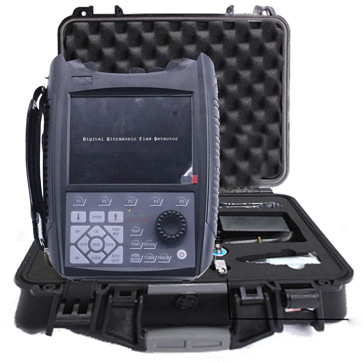
Figure 4.1: Front view of the SUB100 detector with its display and control buttons.

Figure 4.2: Side view of the SUB100, showing its robust casing and wristlet attachment.

Figure 4.3: Top view of the SUB100, displaying the BNC probe connectors and USB port.
4.2 Charging the Device
The SUB100 is powered by an internal rechargeable battery. Before first use, fully charge the device using the provided charger. Connect the charger to the device's power input port and then to a suitable power outlet. The charging indicator will show the charging status.
4.3 Connecting Probes
Select the appropriate probe (Normal or Angle) for your inspection task. Connect the probe cable to one of the BNC connectors on the top of the SUB100 unit. Ensure the connection is secure to prevent signal loss.
4.4 Powering On/Off
Press and hold the power button located on the control panel to turn the device on or off. The LCD screen will illuminate upon successful power-on.
5. Operating Instructions
5.1 Basic Interface and Navigation
The SUB100 features a 640×480, 65536 Colors LCD screen for displaying scan data and settings. Navigation is performed using the control buttons and rotary encoder on the front panel. Familiarize yourself with the function keys (F1-F6), arrow keys, ENTER, and rotary knob for menu selection and parameter adjustment.

Figure 5.1: SUB100 in operation, showing an A-scan display with a connected probe.
5.2 Calibration
Before performing any inspection, it is crucial to calibrate the device. Calibration typically involves setting the sound velocity, probe delay, and gain using a known reference block. Refer to the on-screen menu for detailed calibration procedures specific to your application and probe type.
5.3 Performing a Scan
- Select Mode: Choose between A-scan or B-scan display modes as required for your inspection.
- Apply Couplant: Apply a suitable ultrasonic couplant to the surface of the material to be inspected and to the face of the probe.
- Position Probe: Place the probe firmly on the couplant-covered surface.
- Adjust Parameters: Adjust parameters such as Testing Range (0-9999mm), Velocity Range (1000-9999m/s), and Gain (0dB-110dB) to optimize the signal display.
- Interpret Display: Observe the waveform on the screen to identify flaws or measure thickness. The display delay can be adjusted from -20µs to +3400µs, and probe delay from 0µs to 99.99µs for precise measurements.
5.4 Data Storage and Transfer
The device has a 1GB storage capacity for saving inspection data. Use the PC software and USB disk provided to transfer data to a computer for further analysis and reporting.
6. Maintenance
6.1 Cleaning
Regularly clean the device's exterior with a soft, dry cloth. For stubborn dirt, a slightly damp cloth with mild detergent can be used, ensuring no liquid enters the device. Clean the probe faces thoroughly after each use to remove couplant residue.
6.2 Storage
When not in use, store the SUB100 and its accessories in the provided protective hard case in a cool, dry place, away from direct sunlight and extreme temperatures. Ensure the battery is partially charged (around 50%) for long-term storage to prolong battery life.
6.3 Battery Care
To maintain optimal battery performance, avoid fully discharging the battery frequently. Recharge the device when the battery level is low. If the device will not be used for an extended period, charge it periodically (e.g., every 3-6 months) to prevent deep discharge.
7. Troubleshooting
This section addresses common issues you might encounter with your SUB100 unit.
- Device does not power on: Ensure the battery is charged. Connect the charger and attempt to power on. If the issue persists, contact customer support.
- No signal on screen: Check probe connection. Ensure couplant is applied correctly. Verify gain settings are appropriate for the material and probe.
- Inaccurate readings: Recalibrate the device with a known reference block. Check probe wear and tear. Ensure correct material velocity is set.
- Screen display issues: If the screen is frozen or unresponsive, try restarting the device. If the problem continues, contact support.
8. Technical Specifications
| Parameter | Specification |
|---|---|
| Model Number | SUB100 |
| Testing Range | 0~9999mm |
| Velocity Range | 1000~9999m/s |
| Gain Range | 0dB~110dB |
| Sampling Rate | 100MHz |
| Display Delay | -20µs~+3400µs |
| Probe Delay | 0µs~99.99µs |
| Working Frequency | 0.2~15MHz |
| Compatible Probe Types | 4 (as per description) / 6 (as per feature bullets) - Note: Please refer to device for exact number. |
| Noise Level | ≤10% |
| Transmit Voltage | 5 levels optional |
| Transmit Pulse | Square wave |
| Probe Damping | 4 levels optional |
| Pulse Width | 50ns~1000ns |
| Probe Repeating Frequency | 10~2000Hz |
| Surplus Sensitivity | >62dB |
| Resolution | >40dB(5P14) |
| Linear Inhibition | 0~80% (Digital suppression) |
| Vertical Linear Error | ≤3% |
| Horizontal Linear Error | ≤0.1% |
| Dynamic Range | Less 100dB |
| Storage Capacity | 1GB |
| Working Temperature | -10℃~50℃ |
| Working Humidity | 20%~95% RH |
| Screen | 640×480, 65536 Colors LCD |
| Material | Plastic |
| Power Source | Battery Powered |
| International Protection Rating | IP54 |
| Item Weight | 90 Pounds (approx. 40.82 kg) |
| Parcel Dimensions | 30 x 20 x 10 cm |
9. Warranty Information
Please refer to the warranty card included in your package for detailed warranty terms and conditions. Typically, VTSYIQI products come with a limited warranty covering manufacturing defects. Keep your purchase receipt as proof of purchase.
10. Customer Support
For technical assistance, troubleshooting not covered in this manual, or warranty claims, please contact VTSYIQI customer support. You can find contact information on the official VTSYIQI website or through your retailer.
Visit the official VTSYIQI Store for more information.
11. Video Resources
No relevant official seller videos were found for embedding in this manual based on the provided product data.