
1. Introduction
This manual provides essential information for the safe and efficient operation of your EPEVER® ET6415BND MPPT Charge Controller. Please read this manual thoroughly before installation and use to ensure optimal performance and longevity of the device.
The EPEVER® eTracer series is an advanced Maximum Power Point Tracking (MPPT) controller designed for off-grid photovoltaic (PV) systems. It features an intelligent tracking algorithm to maximize energy yield from PV modules under various weather conditions, offering high efficiency and low power dissipation. This controller also supports data logging for up to 450 days via network connection.
2. Safety Information
Please observe the following safety precautions during installation and operation:
- Ensure all wiring is correct and secure before powering on the controller.
- Do not attempt to disassemble or repair the controller yourself. Refer to qualified personnel.
- Install the controller in a well-ventilated area, away from flammable materials and direct sunlight.
- Wear appropriate personal protective equipment (PPE) when working with electrical systems.
- Disconnect all power sources (PV and battery) before performing any maintenance or wiring.
- The battery bank must be properly fused and protected.
3. Product Features
- Advanced Maximum Power Point Tracking (MPPT) technology for optimal energy harvesting.
- High tracking efficiency of up to 98% and peak conversion efficiency of 98%.
- Supports 12V/24V/36V/48V DC battery systems with auto-recognition.
- Maximum PV input voltage of 150V.
- Comprehensive electronic protection against overcharge, over-discharge, overload, short circuit, and reverse polarity.
- LCD display for real-time system information and parameter settings.
- RS485 communication port for external display, PC software, or remote monitoring.
- Up to 450 days of data logging capability.
4. Product Overview


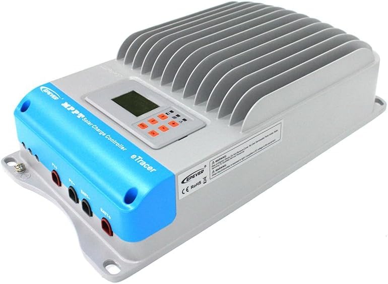
5. Setup and Installation
5.1 Unpacking
Carefully remove the charge controller from its packaging. Inspect the unit for any signs of damage during transit. Retain the packaging for future transport or storage.
5.2 Mounting
- Choose a mounting location that is dry, well-ventilated, and protected from direct sunlight, high temperatures, and moisture.
- Ensure there is sufficient clearance around the controller for air circulation, especially above and below the heat sink fins.
- Mount the controller vertically on a non-flammable surface using appropriate screws and anchors.
5.3 Wiring Connections
Important: Always connect the battery first, then the PV array. Disconnect in the reverse order (PV first, then battery).
- Battery Connection: Connect the positive (+) and negative (-) terminals of the battery bank to the BATT+ and BATT- terminals on the controller, respectively. Ensure correct polarity.
- PV Array Connection: Connect the positive (+) and negative (-) terminals of the PV array to the PV+ and PV- terminals on the controller, respectively. Ensure correct polarity.
- Grounding: Connect the grounding terminal of the controller to an earth ground. The controller has negative grounding.
5.4 Initial Power-Up
Once all connections are secure, the controller will automatically detect the battery voltage and begin operation. The LCD display will illuminate, showing system status and parameters.
6. Operating Instructions
6.1 LCD Display and Buttons
The controller features an LCD display and several buttons for navigation and setting adjustments:
- ESC: Exit current menu or return to previous screen.
- UP/DOWN Arrows: Navigate through menus and adjust parameter values.
- OK: Confirm selection or enter a submenu.
6.2 Monitoring Data
The LCD display cycles through various parameters, including PV voltage, battery voltage, charging current, and power. Use the UP/DOWN arrows to manually scroll through the data screens.
6.3 Parameter Settings
To enter the parameter setting mode, press and hold the OK button. Use the UP/DOWN arrows to select the desired parameter and OK to confirm. Adjust the value using UP/DOWN and confirm with OK. Refer to the detailed parameter list in the full product manual for specific settings.
6.4 Data Logging
The eTracer controller can log up to 450 days of operational data. This data can be accessed and analyzed via the RS485 communication port using compatible PC software or an external display unit (sold separately).
7. Maintenance
Regular maintenance ensures the longevity and optimal performance of your charge controller:
- Cleaning: Periodically clean the controller's exterior with a dry cloth. Ensure the heat sink fins are free of dust and debris to maintain proper cooling.
- Connection Checks: Annually inspect all wiring connections for tightness and corrosion. Loose connections can cause overheating and poor performance.
- Environmental Conditions: Verify that the installation environment remains within the specified operating temperature range and humidity levels.
- Battery Health: Monitor your battery bank's health regularly, as recommended by the battery manufacturer.
8. Troubleshooting
This section addresses common issues you might encounter. For more complex problems, contact customer support.
| Problem | Possible Cause | Solution |
|---|---|---|
| Controller not powering on | Battery not connected or low voltage; reverse polarity. | Check battery connections and voltage. Ensure correct polarity. Charge battery if too low. |
| No PV charging | PV array not connected; low sunlight; PV reverse polarity; PV voltage too low/high. | Check PV connections and polarity. Verify sufficient sunlight. Ensure PV voltage is within controller's operating range. |
| Low charging current | Insufficient PV power; high battery internal resistance; high ambient temperature. | Check PV array for shading or dirt. Inspect battery health. Ensure adequate ventilation around controller. |
| Error code displayed | Specific system fault (e.g., over-voltage, over-temperature). | Refer to the full product manual for a list of error codes and their corresponding solutions. Address the underlying issue. |
9. Specifications
| Parameter | Value |
|---|---|
| Model Number | eTracer6415BND (60A, 12/24/36/48V) |
| Battery Rated Voltage | 12V/24V/36V/48V DC Auto |
| Rated Charge Current | 60A |
| Max. PV Input Voltage | 150V |
| Max. Module Power (12V) | 800W |
| Max. Module Power (24V) | 1600W |
| Max. Module Power (36V) | 2400W |
| Max. Module Power (48V) | 3200W |
| Grounding | Negative |
| Operating Temperature | -25 °C to +55 °C |
| Protection Class | IP20 |
| Product Dimensions | 28.5 x 20.3 x 12.1 cm |
| Item Weight | 6.38 Kilograms |
| Material | Plastic |
| Display Type | LCD or LED |
10. Warranty and Support
10.1 Warranty Information
This EPEVER® ET6415BND MPPT Charge Controller comes with a 2-year manufacturer's warranty from the date of purchase. This warranty covers defects in materials and workmanship under normal use. It does not cover damage caused by improper installation, misuse, accidents, unauthorized repairs, or natural disasters.
10.2 Customer Support
For technical assistance, warranty claims, or further inquiries, please contact your authorized EPEVER® dealer or visit the official EPEVER® website for support resources. When contacting support, please have your product model number and purchase information ready.