
1. Introduction
This manual provides essential information for the installation, operation, maintenance, and troubleshooting of your Juniper Networks EX3400-48P Ethernet Switch. The EX3400-48P is designed to deliver a high-performance, flexible, and cost-effective solution for demanding data, voice, and video enterprise access environments. It supports Juniper Networks Virtual Chassis technology for simplified network operations.
2. Safety Information
Please read and understand all safety instructions before installing or operating the device. Failure to follow these guidelines may result in injury or damage to the equipment.
- Ensure proper grounding of the equipment.
- Do not operate the switch in wet or damp conditions.
- Use only the power supply provided or approved by Juniper Networks.
- Avoid blocking ventilation openings to prevent overheating.
- Refer to qualified service personnel for any servicing not described in this manual.
3. Product Overview
The Juniper Networks EX3400-48P is a 48-port Power over Ethernet (PoE+) capable Ethernet switch. It features a compact design suitable for rack mounting and offers various connectivity options.
3.1. Physical Components
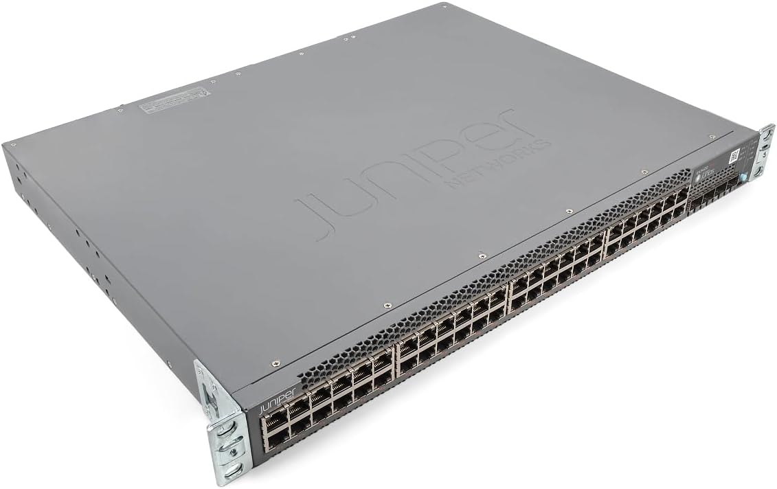
Figure 1: Angled view of the Juniper EX3400-48P Ethernet Switch, showing the top and front panels with the Juniper Networks logo.

Figure 2: Front view of the EX3400-48P switch, highlighting the 48 Ethernet ports, uplink ports, and status LEDs.

Figure 3: Rear view of the EX3400-48P, displaying the modular power supply bay, fan modules, management (MGMT) port, and console (CON) port.

Figure 4: Angled rear view of the EX3400-48P, showing the power supply unit partially extracted, illustrating its modular design.
3.2. Front Panel Features
- 48 x 10/100/1000BASE-T Ethernet Ports: For connecting network devices.
- Uplink Ports: SFP/SFP+ ports for high-speed connections to other switches or routers.
- Status LEDs: Indicators for system status, port activity, and PoE status.
3.3. Rear Panel Features
- Power Supply Bay: Houses the modular power supply unit.
- Fan Modules: Provide cooling for the system.
- Management (MGMT) Port: An out-of-band Ethernet port for device management.
- Console (CON) Port: For local serial console access.
4. Setup
4.1. Unpacking and Inspection
Carefully remove the switch from its packaging. Inspect the device for any signs of physical damage. Report any damage to your supplier immediately.
4.2. Rack Mounting
The EX3400-48P is designed for standard 19-inch rack installation. Use the provided rack-mount brackets and screws to secure the switch in the rack. Ensure adequate space for airflow around the unit.
4.3. Power Connection
- Ensure the power switch on the rear panel is in the OFF position.
- Connect the power cord to the power supply unit on the rear of the switch.
- Plug the other end of the power cord into a grounded AC power outlet.
- Flip the power switch to the ON position. The system status LED should illuminate.
4.4. Initial Configuration
For initial configuration, connect a console cable from your computer to the console port on the rear of the switch. Use a terminal emulation program (e.g., PuTTY, Tera Term) with the following settings:
- Baud rate: 9600
- Data bits: 8
- Parity: None
- Stop bits: 1
- Flow control: None
Follow the on-screen prompts to set up basic network parameters such as IP address, subnet mask, and default gateway.
5. Operating
5.1. Powering On/Off
- Power On: After connecting the power cord, press the power switch to the ON position. The switch will perform a power-on self-test (POST).
- Power Off: To power off, press the power switch to the OFF position. For a controlled shutdown, it is recommended to save the configuration and issue a shutdown command via the command-line interface (CLI) before physically powering off.
5.2. LED Indicators
The front panel LEDs provide visual status of the switch's operation:
- SYS LED: Indicates overall system status (e.g., green for normal operation, amber for warning, red for critical error).
- ALM LED: Indicates alarm status.
- PoE LED: Indicates Power over Ethernet status.
- Port LEDs: Indicate link status and activity for each Ethernet port.
5.3. Network Configuration
The EX3400-48P can be configured via its command-line interface (CLI) or a web-based graphical user interface (GUI) if enabled. Common configurations include:
- VLAN creation and assignment.
- Port security settings.
- Routing protocols.
- Quality of Service (QoS) settings.
- Spanning Tree Protocol (STP) configuration.
Refer to the Juniper Networks documentation for detailed configuration guides specific to Junos OS.
6. Maintenance
6.1. Firmware Updates
Regularly check the Juniper Networks support website for the latest Junos OS firmware updates. Keeping the firmware up-to-date ensures optimal performance, security, and access to new features. Follow the instructions provided with the firmware package for the update procedure.
6.2. Cleaning
Keep the switch clean and free of dust. Use a soft, dry cloth to wipe the exterior. For ventilation openings, use compressed air to remove dust buildup. Ensure the switch is powered off before cleaning.
6.3. Modular Component Replacement
The EX3400-48P features modular power supplies and fan trays. If a component fails, it can be replaced without powering down the entire switch (hot-swappable). Refer to the Juniper Networks hardware guide for specific replacement procedures.
7. Troubleshooting
This section provides solutions to common issues you might encounter.
7.1. No Power
- Verify the power cord is securely connected to both the switch and the power outlet.
- Check if the power outlet is functional.
- Ensure the power switch on the rear panel is in the ON position.
- Inspect the power supply unit for any fault indicators.
7.2. No Link on Port
- Check the Ethernet cable connection at both ends.
- Ensure the connected device is powered on and functioning correctly.
- Try a different port on the switch.
- Verify the cable is not damaged and meets specifications (e.g., Cat5e or higher).
7.3. Network Connectivity Issues
- Verify IP address, subnet mask, and gateway settings on the switch and connected devices.
- Check VLAN configurations if applicable.
- Use diagnostic tools like
pingandtraceroutefrom the switch CLI. - Consult system logs for error messages.
8. Specifications
The following table outlines the technical specifications for the Juniper Networks EX3400-48P Ethernet Switch:
| Feature | Specification |
|---|---|
| Model Number | EX3400-48P |
| Number of Ports | 48 |
| Interface Type | SFP/SFP+ |
| Data Transfer Rate | 336 Gigabits Per Second |
| Voltage | 48 Volts (DC) |
| Case Material | Metal |
| Upper Temperature Rating | 50 Degrees Celsius |
| Product Dimensions | 17.2 x 13.78 x 1.73 inches |
| Item Weight | 12.65 pounds |
| Manufacturer | Juniper |
| UPC | 832938071001 |
9. Warranty and Support
9.1. Product Warranty
This product is typically covered by a manufacturer's warranty. Please refer to the specific warranty terms provided at the time of purchase or on the official Juniper Networks website. A 30-day return policy may apply depending on the vendor.
9.2. Technical Support
For technical assistance, documentation, software downloads, and further support, please visit the official Juniper Networks support website. You may also contact your authorized Juniper Networks reseller for local support options.


