
1. Introduction
The WINGONEER Optical Endstop Limit Switch is a reliable component designed for precise position detection in 3D printers and various CNC applications. This optical limit switch provides a non-contact detection method, offering durability and accuracy. It is compatible with popular control boards such as RAMPS 1.4.
2. Product Features
- Optical Limit Switch: Utilizes an optical sensor for precise and repeatable end-stop detection.
- RAMPS 1.4 Compatibility: Designed to integrate seamlessly with RAMPS 1.4 control boards.
- Reliable Operation: Offers a durable and accurate solution for axis limiting in 3D printers and CNC tools.
- Compact Design: Small form factor for easy integration into various setups.
3. Package Contents
Each package contains the following items:
- 5 x WINGONEER Optical Endstop Limit Switch modules
- 5 x Connection cables

Image 1: WINGONEER Optical Endstop Limit Switch module with its connection cable.
4. Setup and Installation
Follow these steps to properly install your WINGONEER Optical Endstop Limit Switch:
- Mounting the Endstop: Securely attach the optical endstop module to your 3D printer or CNC machine frame at the desired limit position. Ensure that the optical slot is clear and accessible for the moving part to interrupt the light beam. The module typically has mounting holes for screws.
- Connecting the Cable: Connect one end of the provided 3-pin cable to the endstop module's connector. The connector is usually keyed to prevent incorrect insertion.
- Connecting to Control Board: Connect the other end of the cable to the designated endstop pins on your RAMPS 1.4 board or other compatible control board. Refer to your control board's documentation for the correct pin assignments (typically VCC, GND, and Signal).

Image 2: Close-up view of the optical endstop module, showing the sensor and connection pins.
- Testing the Connection: Before powering on, double-check all connections to ensure they are firm and correctly oriented. Incorrect wiring can damage the module or control board.
5. Operating Instructions
Once installed, the optical endstop operates by detecting the presence or absence of an object interrupting its light beam. When the moving part of your 3D printer or CNC machine (e.g., the print head or bed) reaches the limit, it passes through the optical slot, blocking the light. This change in light detection triggers the endstop signal.
- Firmware Configuration: Ensure your 3D printer or CNC machine's firmware is configured to recognize optical endstops. This typically involves setting the correct endstop type and logic (normally open or normally closed, depending on the specific module and desired behavior). Consult your firmware documentation (e.g., Marlin, Repetier) for detailed configuration steps.
- Calibration: After initial setup and firmware configuration, perform a calibration test to verify that the endstop triggers correctly at the desired physical limit. Manually move the axis towards the endstop and observe the endstop status in your control software (e.g., Pronterface, OctoPrint).
- Normal Operation: During normal operation, the endstop will automatically signal the control board when an axis reaches its physical limit, preventing further movement in that direction and ensuring proper homing sequences.
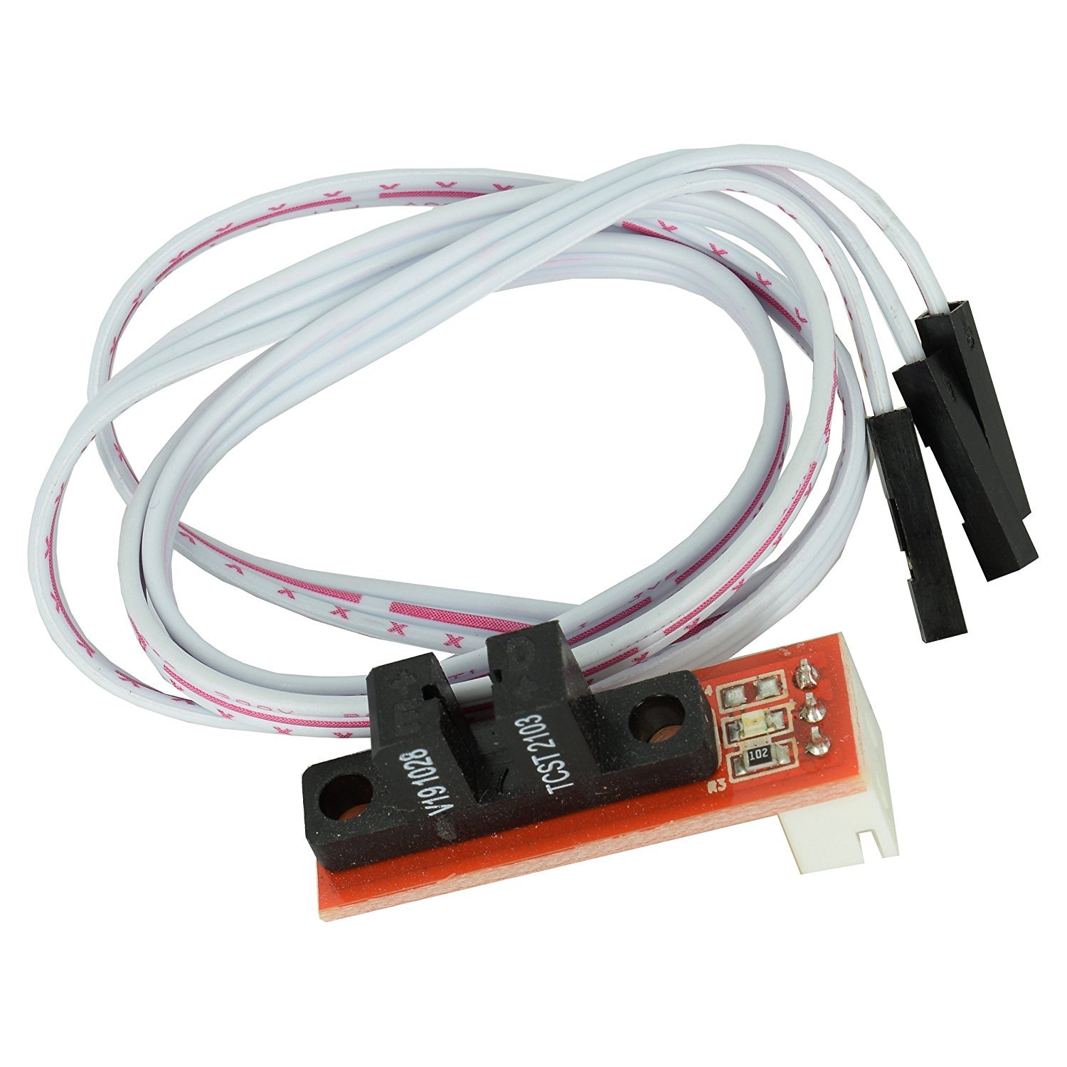
Image 3: The optical endstop showing the slot where the moving part interrupts the light beam.
6. Maintenance
The WINGONEER Optical Endstop Limit Switch requires minimal maintenance due to its non-contact design. However, consider the following for optimal performance:
- Keep Clean: Periodically inspect the optical slot for dust, debris, or filament particles that could obstruct the light beam. Use a soft, dry brush or compressed air to gently clean the slot if necessary.
- Check Connections: Ensure all cable connections remain secure and free from damage.
- Avoid Physical Impact: While durable, avoid subjecting the module to excessive physical force or impact, which could misalign the optical components.
7. Troubleshooting
If you encounter issues with your optical endstop, consider the following troubleshooting steps:
- Endstop Not Triggering:
- Verify that the moving part fully interrupts the light beam in the optical slot.
- Check cable connections for proper seating and continuity.
- Ensure the endstop is correctly configured in your printer's firmware (e.g., correct pin, logic).
- Inspect the optical slot for any obstructions (dust, debris).
- Endstop Always Triggered:
- Ensure nothing is permanently blocking the optical slot.
- Check for short circuits in the wiring or on the module itself.
- Verify firmware configuration for correct endstop logic.
- Intermittent Triggering:
- Check for loose connections or damaged cables.
- Ensure the optical slot is clean and free from intermittent obstructions.
- Verify stable power supply to the control board and endstop.
8. Specifications
| Manufacturer | WINGONEER |
| Model Number | 1034 |
| Module Dimensions (approx.) | 32mm x 10mm (1.26" x 0.39") |
| Type | Optical Limit Switch |
| Compatibility | RAMPS 1.4, various 3D printers and CNC tools |
| Connection Type | Wired (3-pin cable included) |
| Batteries Required | No |
| Items per Package | 5 modules with cables |
9. Warranty and Support
Information regarding specific warranty terms and support for the WINGONEER Optical Endstop Limit Switch is not provided in the product details. For any support inquiries, please refer to the vendor or retailer from whom the product was purchased.