
1. Introduction
The BSIDE ZT100 is a compact, auto-ranging digital multimeter designed for measuring AC/DC voltage, AC/DC current, resistance, capacitance, and frequency. It features a 6000-count display with backlight, data hold function, and automatic power-off for energy conservation. This manual provides essential information for safe and effective use of the device.

Figure 1: The BSIDE ZT100 Digital Multimeter is designed for portability, fitting conveniently into a pocket for easy transport.
2. Safety Information
Always observe safety precautions when using this multimeter to prevent electric shock or personal injury. Read all instructions before use.
- Do not exceed the maximum input values for any range.
- Exercise extreme caution when working with voltages above 30V AC RMS, 42V peak, or 60V DC. These voltages pose a shock hazard.
- Before measuring current, ensure the circuit is de-energized and the multimeter is connected in series.
- Before measuring resistance or capacitance, ensure the circuit is de-energized and all capacitors are discharged.
- Inspect test leads for damaged insulation or exposed metal before use. Replace if damaged.
- Do not operate the multimeter if it appears damaged or if the battery cover is not properly closed.
- Refer to the manual for correct fuse ratings if replacement is necessary.
3. Product Overview
The BSIDE ZT100 features a clear LCD display, function selector dial, input jacks, and control buttons. Familiarize yourself with these components before operation.

Figure 2: Front view of the BSIDE ZT100 Digital Multimeter, highlighting the display, rotary switch, and input terminals.
4. Setup
4.1 Battery Installation
The ZT100 multimeter requires two AAA batteries (not included) for operation. Follow these steps to install them:
- Ensure the multimeter is powered off and disconnect any test leads.
- Locate the battery compartment cover on the back of the device.
- Use a screwdriver to loosen the screw securing the battery cover.
- Remove the battery cover.
- Insert two AAA batteries, observing the correct polarity (+ and -) as indicated inside the compartment.
- Replace the battery cover and tighten the screw securely.
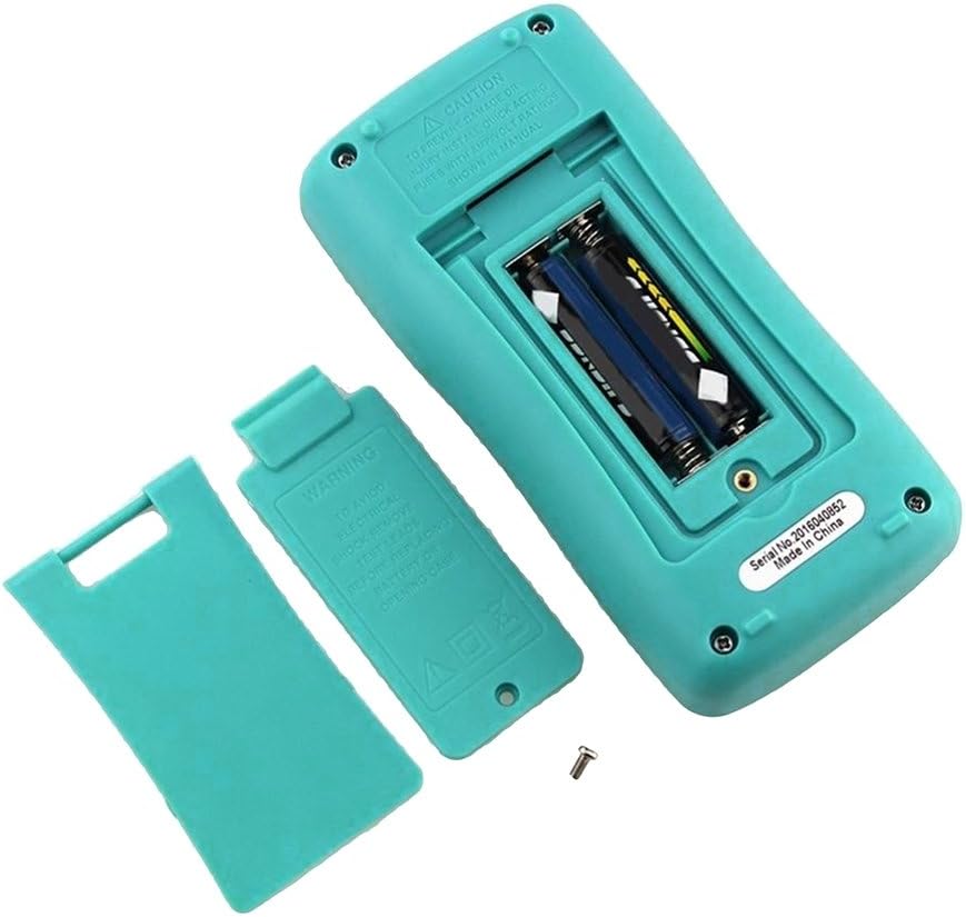
Figure 3: Rear view of the multimeter with the battery compartment open, showing the correct placement of AAA batteries.
5. Operating Instructions
The ZT100 features auto-ranging, simplifying measurements by automatically selecting the appropriate range.
5.1 Power On/Off
Rotate the function selector dial from the 'OFF' position to any measurement function to power on the device. To power off, rotate the dial back to 'OFF'. The device also features an auto power-off function after a period of inactivity.
5.2 DC Voltage Measurement
- Set the function selector dial to the 'V=' position.
- Connect the red test lead to the 'VΩmA' input jack and the black test lead to the 'COM' input jack.
- Connect the test probes across the component or circuit to be measured.
- Read the voltage value on the display.
5.3 AC Voltage Measurement
- Set the function selector dial to the 'V~' position.
- Connect the red test lead to the 'VΩmA' input jack and the black test lead to the 'COM' input jack.
- Connect the test probes across the AC voltage source.
- Read the voltage value on the display.
5.4 DC/AC Current Measurement
Caution: To avoid damage to the meter or injury, never attempt to measure current on a circuit with voltage exceeding 250V.
- Set the function selector dial to the 'A=' or 'A~' position for DC or AC current, respectively.
- For currents up to 400mA, connect the red test lead to the 'VΩmA' input jack. For currents up to 10A, connect the red test lead to the '10A' input jack. Connect the black test lead to the 'COM' input jack.
- Open the circuit where current is to be measured and connect the multimeter in series.
- Read the current value on the display.
5.5 Resistance Measurement
Caution: Ensure the circuit is de-energized and all capacitors are discharged before measuring resistance.
- Set the function selector dial to the 'Ω' position.
- Connect the red test lead to the 'VΩmA' input jack and the black test lead to the 'COM' input jack.
- Connect the test probes across the resistor or component.
- Read the resistance value on the display.
5.6 Capacitance Measurement
Caution: Ensure the capacitor is fully discharged before measurement to prevent damage to the meter.
- Set the function selector dial to the 'F' position.
- Connect the red test lead to the 'VΩmA' input jack and the black test lead to the 'COM' input jack.
- Connect the test probes across the capacitor terminals.
- Read the capacitance value on the display.
5.7 Frequency Measurement
- Set the function selector dial to the 'Hz' position.
- Connect the red test lead to the 'VΩmA' input jack and the black test lead to the 'COM' input jack.
- Connect the test probes across the signal source.
- Read the frequency value on the display.
5.8 Data Hold Function
Press the 'HOLD' button to freeze the current reading on the display. Press it again to release the hold function.
6. Maintenance
6.1 Cleaning
Wipe the case with a damp cloth and mild detergent. Do not use abrasives or solvents. Keep the input terminals free of dirt and moisture.
6.2 Battery Replacement
When the low battery indicator appears on the display, replace the batteries promptly to ensure accurate readings. Refer to Section 4.1 for battery installation instructions. Always use two new AAA batteries of the same type.

Figure 4: The empty battery compartment of the BSIDE ZT100, showing the spring contacts and battery orientation markings.
6.3 Fuse Replacement
The multimeter is protected by internal fuses. If the current measurement function fails, the fuse may need replacement. Fuse replacement should only be performed by qualified personnel. Use only fuses with the specified ratings to prevent damage or injury.
7. Troubleshooting
- No display or faint display:
Check battery installation and polarity. Replace batteries if low battery indicator is present or if display remains faint. - Incorrect readings:
Ensure test leads are properly connected to the correct input jacks. Verify the function selector dial is set to the appropriate measurement type. Check for damaged test leads. Ensure the circuit is de-energized for resistance/capacitance measurements. - Current measurement not working:
Check if the fuse is blown. Ensure the multimeter is connected in series with the circuit. Verify the correct input jack (mA or 10A) is used. - Auto power-off:
This is a normal feature to conserve battery life. The meter will power off after a period of inactivity. Rotate the function dial or press a button to reactivate.
8. Specifications
| Feature | Specification |
|---|---|
| Max. Display | 6000 counts |
| Ranging | Auto |
| Update Rate | 3 times / second |
| DC Voltage | 400mV / 4V / 40V / 400V / 600V |
| AC Voltage | 400mV / 4V / 40V / 400V / 600V |
| DC Current | 40mA / 400mA / 10A |
| AC Current | 40mA / 400mA / 10A |
| Resistance | 400Ω / 4KΩ / 40KΩ / 400KΩ / 4MΩ / 40MΩ |
| Frequency | 99.5Hz / 999.5Hz / 9.999KHz / 99.99KHz / 999.9KHz / 9.999MHz |
| Capacitance | 4nF / 40nF / 400nF / 4uF / 40uF / 400uF / 1000uF / 4000uF |
| Low Battery Indicator | Yes |
| Data Hold | Yes |
| Auto Power Off | Yes |
| Power Source | 2 x AAA Battery |
9. Warranty and Support
For warranty information and technical support, please refer to the documentation provided with your purchase or contact the seller directly. Keep your purchase receipt as proof of purchase.


