
1. Introduction
This manual provides essential information for the proper installation, operation, and maintenance of the Allen-Bradley 22-HIM-C2S PowerFlex Operator Interface Keypad. This device is designed to provide local control and display capabilities for compatible PowerFlex variable frequency drives. Please read this manual thoroughly before attempting to install or operate the keypad.
2. Product Overview
The Allen-Bradley 22-HIM-C2S is a Human Interface Module (HIM) that serves as a local operator interface for PowerFlex drives. It features an LCD display and a set of tactile buttons for navigation, parameter adjustment, and drive control.

Figure 2.1: Front view of the Allen-Bradley 22-HIM-C2S PowerFlex Operator Interface Keypad. This image displays the front panel of the 22-HIM-C2S keypad, featuring an LCD screen at the top and a series of control buttons below. The buttons include 'Esc', 'Sel', 'Disp', 'Remove', 'ALT', 'LANG', up/down arrows, 'Jog', 'Run' (green), 'Stop' (red), and navigation arrows.

Figure 2.2: Side view of the Allen-Bradley 22-HIM-C2S PowerFlex Operator Interface Keypad. A side profile of the 22-HIM-C2S keypad, showing its compact form factor and the slight elevation of the control panel.

Figure 2.3: Rear view of the Allen-Bradley 22-HIM-C2S PowerFlex Operator Interface Keypad showing internal circuitry. This image shows the rear of the keypad with the cover removed, revealing the main circuit board, connectors, and mounting screws. The Allen-Bradley branding and model number '22-HIM-C2S' are visible on a label.
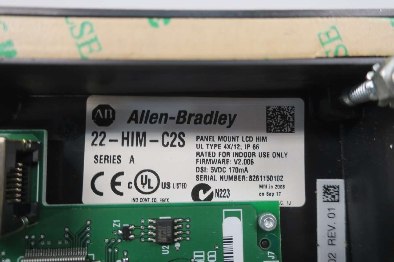
Figure 2.4: Close-up of the Allen-Bradley 22-HIM-C2S product label on the internal circuit board. A detailed view of the product label on the internal circuit board, indicating 'Allen-Bradley 22-HIM-C2S', 'SERIES A', 'PANEL MOUNT LCD HIM', 'UL TYPE 4X/12; IP 66', 'RATED FOR INDOOR USE ONLY', 'FIRMWARE: V2.006', 'DSI: 5VDC 170mA', and 'SERIAL NUMBER: 8261150102'.

Figure 2.5: Close-up of the internal circuit board with Rockwell Automation branding. A close-up of another section of the internal circuit board, showing a barcode and 'Rockwell Automation' branding, along with part numbers 'M003821329' and '316553-A01'.
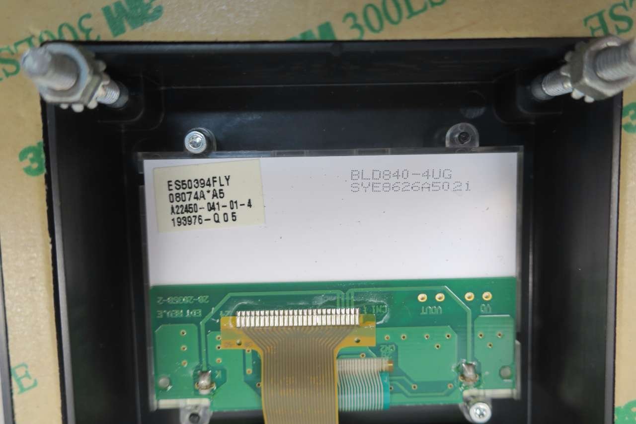
Figure 2.6: Close-up of the LCD connection on the internal circuit board. This image provides a detailed view of the flexible ribbon cable connecting the LCD display to the main circuit board, highlighting the delicate nature of the internal components.
2.1 Keypad Button Functions
- Esc (Escape): Used to exit a menu or screen without saving changes, or to return to the previous display.
- Sel (Select): Used to confirm a selection or enter a menu.
- Disp (Display): Toggles between different display modes or parameters.
- Remove: Typically used to delete characters during data entry.
- ALT (Alternate): Provides access to alternate functions or shift operations for certain keys.
- LANG (Language): Used to change the display language.
- Up/Down Arrows: Used to navigate through menus, increment/decrement values, or scroll through lists.
- Jog: Initiates a jog operation for the connected drive.
- Run (Green Button): Starts the connected drive.
- Stop (Red Button): Stops the connected drive.
3. Setup and Installation
The 22-HIM-C2S keypad is designed for panel mounting. Proper installation is crucial for reliable operation and safety. It is recommended that installation be performed by qualified personnel.
3.1 Mounting
- Ensure all power to the drive and control system is disconnected before beginning installation.
- Cut a rectangular opening in the control panel according to the dimensions specified in the product documentation (refer to the drive's manual for exact cutout dimensions).
- Insert the 22-HIM-C2S keypad into the cutout from the front of the panel.
- Secure the keypad using the provided mounting hardware from the rear of the panel. Ensure a tight seal for the specified IP rating.
3.2 Electrical Connection
- Connect the appropriate communication cable from the 22-HIM-C2S to the designated port on the PowerFlex drive.
- Ensure connections are secure and correctly polarized.
- Verify that the power supply to the keypad (DSI: 5VDC 170mA) meets the specified requirements.
- Once all connections are made, restore power to the drive and control system. The keypad display should illuminate.
4. Operating Instructions
The 22-HIM-C2S keypad allows users to monitor drive status, modify parameters, and control the drive locally. Specific operational details will depend on the PowerFlex drive model it is connected to.
4.1 Basic Navigation
- Upon power-up, the keypad typically displays the drive's status or a default parameter.
- Use the Up/Down Arrows to scroll through parameters or menu options.
- Press Sel to enter a menu or select a parameter for editing.
- Press Esc to return to the previous screen or exit a menu.
4.2 Parameter Adjustment
- Navigate to the desired parameter using the arrow keys and press Sel.
- The parameter value will typically begin to flash, indicating it is editable.
- Use the Up/Down Arrows to change the value.
- Press Sel again to save the new value. Press Esc to discard changes.
4.3 Drive Control
- Press the Green Run Button to start the motor connected to the drive.
- Press the Red Stop Button to stop the motor.
- Press the Jog Button to initiate a momentary jog operation, typically used for testing or positioning.
5. Maintenance
The 22-HIM-C2S keypad is designed for minimal maintenance. Regular inspection and cleaning can help ensure its longevity and proper function.
5.1 Cleaning
- Ensure power is disconnected from the keypad and drive before cleaning.
- Wipe the display and keypad surface with a soft, damp cloth.
- Do not use abrasive cleaners, solvents, or harsh chemicals, as these can damage the plastic and display.
- Avoid spraying liquids directly onto the keypad.
5.2 Environmental Considerations
- The keypad is rated for indoor use only.
- Ensure the operating environment is within the specified temperature and humidity ranges to prevent damage.
- Protect the keypad from excessive dust, moisture, and corrosive substances.
6. Troubleshooting
This section provides basic troubleshooting steps for common issues. For more complex problems, consult the PowerFlex drive's user manual or contact technical support.
6.1 No Display or Unresponsive Keypad
- Check Power: Verify that the drive and control system are powered on and that the keypad is receiving its 5VDC power supply.
- Check Connections: Ensure the communication cable between the keypad and the drive is securely connected at both ends.
- Restart System: Power cycle the drive and keypad to reset the system.
- Inspect for Damage: Visually inspect the keypad for any signs of physical damage or loose connections.
6.2 Incorrect Parameter Values
- Verify Drive Settings: Ensure the drive's configuration allows for parameter changes via the HIM.
- Confirm Save: After changing a parameter, ensure you press Sel to save the new value.
- Refer to Drive Manual: Consult the specific PowerFlex drive manual for parameter definitions and valid ranges.
7. Specifications
| Feature | Specification |
|---|---|
| Model Number | 22-HIM-C2S |
| Part Number | D581161 |
| Series | SER A |
| Type | Panel Mount LCD HIM |
| Enclosure Rating | UL Type 4X/12; IP 66 |
| Usage Environment | Rated for indoor use only |
| Firmware Version | V2.006 |
| DSI Power Supply | 5VDC 170mA |
| Product Dimensions | 7 x 3.75 x 1.5 inches |
| Product Weight | 1.4 Pounds |
| Manufacturer | ALLEN BRADLEY |
| ASIN | B076CQ84N6 |
8. Warranty and Technical Support
Allen-Bradley products are typically covered by a standard manufacturer's warranty. For specific warranty terms and conditions, please refer to the original purchase documentation or contact your authorized Allen-Bradley distributor.
For technical assistance, troubleshooting beyond the scope of this manual, or to obtain replacement parts, please contact Allen-Bradley technical support or your local Rockwell Automation representative. Ensure you have the model number (22-HIM-C2S) and serial number (found on the product label) available when seeking support.