
1. Overview
The DIYmall LoRa32u4 II is a compact, low-power development board designed for long-range wireless communication projects. It integrates an ATmega32u4 microcontroller with a HPD13 915MHz LoRa module and includes a USB battery charging circuit. This board is suitable for applications requiring extended wireless range and efficient power consumption, offering greater flexibility than Bluetooth LE and lower power requirements than Wi-Fi.
Key features include:
- ATmega32u4 microcontroller operating at 8MHz with 3.3V logic/power.
- Integrated 3.3V regulator with 500mA peak current output.
- Native USB support with pre-installed USB bootloader for easy programming and serial debugging.
- Built-in 100mA LiPo charger with a charging status indicator LED.
- Reset button for convenient operation.
- HPD13 LoRa module with digital RSSI, automatic frequency correction, and automatic gain control.

Figure 1: DIYmall LoRa32u4 II Development Board. This image shows the compact size of the board with the attached antenna, highlighting its design for integration into various projects.
2. Setup Instructions
2.1 Package Contents
Verify that your package contains the following items:
- 1 x LoRa32u4 II LoRa module
- 1 x IPEX 1.13 UF.L Antenna
- 1 x JST-PH2.0MM-2P plug cable
2.2 Hardware Connection
Before powering on the board, ensure the antenna is securely connected to the UF.L connector. The board also features a JST-PH2.0MM-2P connector for a LiPo battery, which can be charged via the USB port.
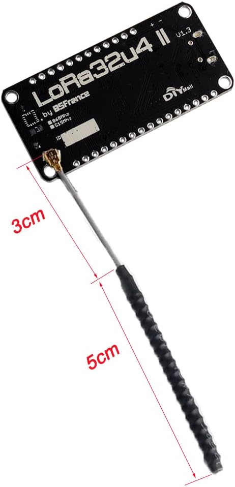
Figure 2: LoRa32u4 II board with antenna dimensions. This image illustrates the physical dimensions of the antenna and its connection point on the board.
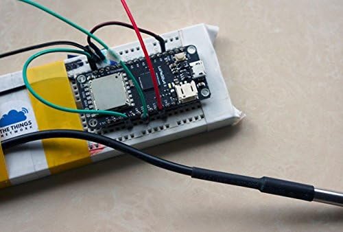
Figure 3: Example setup of LoRa32u4 II board on a breadboard with a connected battery and sensor. This demonstrates a typical application setup for the development board.
2.3 Software Setup (Arduino IDE)
To program the LoRa32u4 II board, you will need the Arduino IDE. Follow these steps:
- Install Arduino IDE: Download and install the latest version of the Arduino IDE from the official Arduino website.
- Add Board Support:
- Go to File > Preferences in the Arduino IDE.
- In the "Additional Boards Manager URLs" field, add the URL for Adafruit Feather 32u4 boards. A common URL is https://adafruit.github.io/arduino-board-index/package_adafruit_index.json.
- Go to Tools > Board > Boards Manager.... Search for "Adafruit AVR Boards" and install it.
- Select your board: Go to Tools > Board and choose "Adafruit Feather 32u4".
- Install LoRa Library:
- Go to Sketch > Include Library > Manage Libraries....
- Search for "LoRa" and install the library by Sandeep Mistry.
- Connect the Board: Connect the LoRa32u4 II board to your computer using a micro-USB cable. The board should appear as a serial port. Select the correct port under Tools > Port.

Figure 4: Screenshot of Arduino IDE demonstrating a basic LoRa sender sketch and serial monitor output. This image provides a visual reference for programming the board.
3. Operating Instructions
3.1 Pinout Diagram
Refer to the pinout diagram for detailed information on the board's connections and functionalities. This diagram is crucial for connecting external sensors, actuators, and understanding the board's capabilities.

Figure 5: Detailed pinout diagram for the LoRa32u4 II V1.3 board. This diagram labels all pins, including power, ground, analog, digital, SPI, I2C, and LoRa specific pins, along with notes on power saving features and integrated sensors.
Power Saving Feature: The battery voltage divider and LiPo charger power are controlled via PB0. Set PB0 HIGH to enable battery monitoring (D9) and battery charging. Set PB0 LOW to disable them.
3.2 LoRa Communication Basics
The LoRa32u4 II board utilizes the LoRa (Long Range) modulation technique, enabling long-distance communication with low power consumption. Key parameters for LoRa communication include:
- Frequency Band: The 915MHz version operates within specific frequency ranges depending on the region.
- Spreading Factor (SF): Affects range and data rate. Higher SF means longer range but lower data rate.
- Bandwidth (BW): The width of the signal used for transmission.
- Coding Rate (CR): Adds redundancy to the data for error correction.
For specific regional frequency bands and channel configurations, refer to the table below:

Figure 6: Table detailing LoRa frequency bands, channels, bandwidth, TX power, SF, and data rates for various regions including Europe, North America, China, Korea, Japan, and India.
When programming, ensure your LoRa settings (frequency, SF, BW) comply with local regulations and match the settings of the receiving LoRa device for successful communication.
3.3 Example Video: LoRa Communication Demonstration
Video 1: A short demonstration of two DIYmall LoRa32u4ii boards communicating. This video visually confirms basic LoRa transmission and reception functionality between two modules.
Video 2: An unboxing and overview of the DIYmall LoRa32u4ii SX1276 module with antenna. This video provides a closer look at the components included and the physical board.
4. Maintenance
The LoRa32u4 II development board requires minimal maintenance. Follow these guidelines to ensure its longevity and reliable operation:
- Storage: Store the board in a dry, anti-static environment when not in use. Avoid extreme temperatures and humidity.
- Cleaning: If necessary, gently clean the board with a soft, dry brush or compressed air to remove dust. Do not use liquids or abrasive cleaners.
- Handling: Always handle the board by its edges to avoid touching components, especially the antenna connector, and to prevent electrostatic discharge.
- Antenna Care: Ensure the antenna is not bent or damaged. A damaged antenna can significantly reduce communication range and performance.
5. Troubleshooting
This section addresses common issues you might encounter with the LoRa32u4 II board.
5.1 Board Not Detected by Computer
- USB Cable: Ensure you are using a data-capable USB cable. Some USB cables are for charging only.
- Drivers: Verify that the necessary USB drivers are installed. For Arduino-compatible boards, these are usually installed with the Arduino IDE.
- Arduino IDE Board Selection: Confirm that "Adafruit Feather 32u4" is selected under Tools > Board and the correct COM port is chosen.
5.2 LoRa Communication Failure
- Antenna Connection: Ensure the antenna is securely connected to the UF.L connector. Loose or missing antennas will severely impact range.
- Frequency Mismatch: Verify that both the sender and receiver LoRa modules are configured to the same frequency band (e.g., 915MHz) and LoRa parameters (Spreading Factor, Bandwidth, Coding Rate).
- Library Issues: Confirm that the Sandeep Mistry LoRa library is correctly installed and updated.
- Power Output: If experiencing very short range, check the transmit power settings in your code. Some users have reported issues with communication between DIYmall modules, suggesting potential differences in transmit power or sensitivity compared to other brands.
- Interference: LoRa performance can be affected by environmental interference. Test in different locations if possible.
5.3 Battery Monitoring Issues
- PB0 Pin: Ensure the PB0 pin is set HIGH in your code to enable the battery voltage divider and charger power for monitoring. Setting it LOW will disable these features.
6. Specifications
| Feature | Detail |
|---|---|
| Brand | DIYmall |
| Model Name | LoRa32u4 II |
| Model Number | DIY0051N+FZ2862 |
| Processor | ATmega32u4 |
| CPU Speed | 8MHz (board operates at 3.3V) |
| RAM Memory Installed Size | 2.5 KB (SRAM) |
| Connectivity Technology | USB |
| LoRa Module | HPD13 (SX1276) |
| Frequency Band | 915MHz (specific regional variations apply) |
| Receive Current | 10 ~ 14mA |
| Operating Temperature | -40 °C to +85 °C |
| Battery Charger | Built-in 100mA LiPo charger |
| Compatible Devices | JST-PH2.0MM-2P compatible devices, LoRa compatible devices |
| Operating System (Example) | FreeRTOS (can be programmed with Arduino IDE) |
7. Warranty and Support
Specific warranty information for the DIYmall LoRa32u4 II Development Board is not provided in the product details. For support, technical inquiries, or warranty claims, please contact DIYmall directly through their official channels or the platform where the product was purchased.
You may find additional resources and community support by searching online forums and communities dedicated to Arduino and LoRa development, particularly those focused on Adafruit Feather 32u4 compatible boards.
Online Resources:
- DIYmall Store: Visit DIYmall Store on Amazon
- General Arduino and LoRa communities for similar boards.