
1. Product Overview
This manual provides detailed instructions for the installation, operation, and maintenance of your ZXTDR 48V 1800W Brushless Motor and Controller Throttle Grip Set. Please read this manual thoroughly before use to ensure proper function and safety.
Advantages of Brushless Motors:
- Reduced Noise: Less electrical and electromagnetic noise compared to brushed motors.
- Extended Lifespan: No brushes to wear out, resulting in approximately triple the lifespan of a brushed motor.
- Low Maintenance: Eliminates the need for brush replacement.
- Energy Efficient: Power consumption is approximately 1/3 of a brushed motor.
- High Efficiency: Brushless motors typically achieve 85-90% efficiency, whereas brushed DC motors are around 75-80% efficient.
Brushless vs. Brushed Motor Comparison:
Brushed and brushless direct current electric motors differ fundamentally in how electric current is transferred to the commutator or electromagnets that drive the rotor. In a brushed motor, current is transferred mechanically via metallic brushes. Conversely, in a brushless motor, the rotor is turned electronically, eliminating the need for physical contacts.
2. Specifications
| Feature | Value |
|---|---|
| Brand | ZXTDR |
| Rated Speed | 4500 RPM |
| Sprocket | 9 tooth for T8F chain |
| Horsepower | 1.8HP (1800 Watts) |
| Voltage | 48V (Controller input) / 5 Volts (Throttle signal) |
| Material | Metal |
| Item Weight | 1.3 Pounds |
| UPC | 190835585572 |
3. Setup and Installation
The controller requires four essential cable groups for basic operation: Battery, Motor, Ignition lock, and Derailleur (throttle). Other functions are optional and can be connected according to your specific application needs.
Detailed Wiring Connections:
- Battery: Thick Black (Power Negative) / Thick Red (Power Positive)
- Motor: Thick Yellow (Motor Negative) / Thick Blue (Motor Positive)
- Ignition Switch: Thin Red (VCC) / Thin Blue
- Indicator: Thin Red (Indicator power output) / Thin Black (Indicator negative)
- Brake: Thin Yellow (Brake signal) / Thin Black (Negative Power)
- Speed Governor (Throttle): Thin Blue (Speed handlebar Signal input) / Thin Black (Negative Power) / Thin Red (5V Positive Power)
- Charge Port: Thin Red (Charge input power Positive) / Thin Black (Power negative)
- Brake Light: Thin Red (Power Positive) / Thin Black (Power negative)
Controller Dimensions

This image provides the physical dimensions of the motor controller, including its length, width, and height, which are crucial for planning installation space.
Motor and Controller Dimensions

This image displays the key dimensions for both the brushless motor and its accompanying controller. It includes measurements such as the motor's shaft outer diameter and overall body dimensions, as well as the controller's length, width, and height, aiding in installation and fitment.
Controller Wire Identification

This image illustrates the various labeled wires extending from the motor controller, indicating their specific functions such as throttle, charging port, hour meter, power lock (ignition), gear selection, inverted gear, Hall sensor wires, indicator light, and brake connections. Each wire is clearly labeled in English and Chinese.
Example Wiring Diagram

This diagram provides a visual guide for connecting the 48V 1800W brushless motor, controller, battery, and other components. It highlights the main connections including the motor wires, battery wires, and various control plugs such as Hall wire, battery indicator, ignition lock, throttle, and braking functions.
Detailed Wiring Diagram for 1800 Watt Brushless DC Motor & Controller
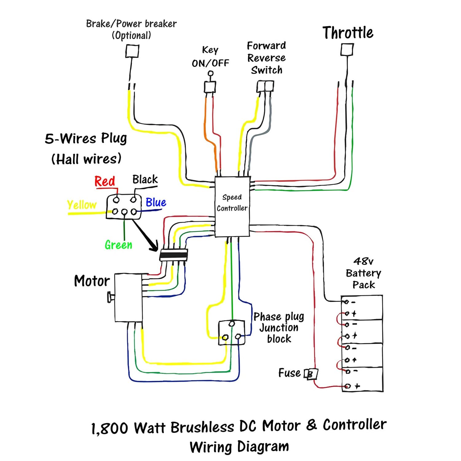
A comprehensive wiring diagram illustrating the connections for the 1800 Watt Brushless DC Motor and its controller. It details the links to the 48V battery pack, motor, speed controller, Hall sensor wires, ignition switch, forward/reverse switch, throttle, and an optional brake/power breaker.
Chain Sprocket Orientation Wiring

This image provides specific wiring adjustments based on the chain sprocket's mounting position (left or right side of the bike). For a left-side installation, certain Hall and phase wires need to be swapped. For a right-side installation, all wires are connected color-to-color.
4. Operation
Throttle Grip Usage
The throttle grip controls the motor's speed. Rotate the grip to increase or decrease power output. Ensure the ignition is on and all connections are secure before operating the system. Always operate the vehicle safely and according to local regulations.
Throttle Grip Dimensions

This image displays the physical dimensions of the throttle grips, including their overall length and inner diameters for proper fitment on handlebars.
5. Maintenance
Brushless motors are renowned for their minimal maintenance requirements due to the absence of physical brushes. Regular maintenance should primarily focus on:
- Inspection: Periodically check all wiring connections for tightness, signs of wear, or damage. Ensure no wires are frayed or exposed.
- Cleaning: Keep the motor and controller free from dirt, dust, and moisture. A clean system ensures optimal performance and helps prevent overheating.
- Sprocket: Inspect the sprocket for any signs of wear, such as chipped or bent teeth, and ensure it is securely attached to the motor shaft. The sprocket is replaceable; ensure any new sprocket has an inner dimension of 8.5x10mm.
Sprocket Details and Replacement

This image provides a close-up of the motor's sprocket, detailing its outer diameter (OD), inner dimensions, and tooth count (T8F 9 teeth). It confirms that the sprocket is replaceable, provided the new one matches the specified inner dimensions of 8.5x10mm.
6. Troubleshooting
This section addresses common issues that may arise during installation or operation and provides potential solutions.
- Controller Not Powering Up:
- Ensure a jumper is correctly placed on the power lock plug for the controller to receive power. Without this connection, the system will not activate.
- Motor Not Running or Running in Reverse:
- A jumper must be placed on the inverter plug (connect black to yellow or black to gray). This connection controls the forward, stop, and reverse functions. If this is not connected, the motor will not run.
- If the motor runs in reverse, swap the thick motor wires: connect the thick controller blue wire to the thick motor green wire, and the thick controller green wire to the thick motor blue wire. The yellow wires should remain connected yellow to yellow.
- At the motor Hall plug, switch the blue and yellow wires. The green wire in the middle should not be moved and should match green to green, red to red, and black to black when connected to the controller Hall plug.
- Motor Speed/Gear Selection Issues:
- The "stalls" plug functions as a speed/gear selector (connect black to green or black to blue). If this connection is not jumped, the motor will typically operate in a medium speed/gear setting.
- Battery Voltage Indicator:
- The "indicator" plug is designed for a 48V battery voltage meter display. Connecting a compatible meter provides a convenient way to monitor if the controller is powered on and the remaining battery level.
- Braking Function:
- The "braking" plug is used to cut off power from the motor when the brake pedal is pressed. A separate switch is required for this function if you intend to utilize it.
7. Warranty and Support
For warranty information, technical support, or assistance with your ZXTDR product, please refer to the seller's official channels or contact ZXTDR customer service directly. Further details and contact information may be available on the ZXTDR Brand Store on Amazon.