
Flysky FS-X6B
Flysky FS-X6B 2.4G PPM i-Bus 6CH Receiver User Manual
Model: FS-X6B
Brand: Flysky
1. Introduction
The Flysky FS-X6B is a compact and versatile 6-channel two-way receiver specifically designed for multi-rotor aircraft. It utilizes the advanced AFHDS 2A (Automatic Frequency Hopping Digital System) protocol, ensuring reliable and stable communication. With its dual omnidirectional antennas and superior noise reduction techniques, the FS-X6B provides excellent signal reception. This manual provides essential information for setting up, operating, and maintaining your FS-X6B receiver.
2. Product Overview
The FS-X6B receiver is engineered for ease of installation and boasts a rich, user-friendly interface. It supports multiple output types, making it highly adaptable for various multi-rotor configurations.

Figure 2.1: Top view of the Flysky FS-X6B receiver, showing the main board, dual antennas, and binding/update buttons.

Figure 2.2: Close-up view of the FS-X6B receiver, highlighting the antenna connections and compact design.
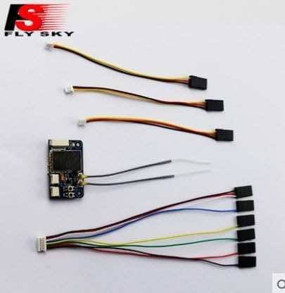
Figure 2.3: The FS-X6B receiver shown with various connection cables, including PWM and i-BUS cables.
3. Features
- 6-Channel Two-Way Receiver: Designed specifically for multi-rotor aircraft.
- AFHDS 2A Protocol: Utilizes Automatic Frequency Hopping Digital System for robust and reliable communication.
- Dual Omnidirectional Antenna: Enhances signal reception and reduces interference.
- Superior Noise Reduction: Advanced techniques for cleaner signal transmission.
- Compact and Easy to Install: Small form factor for convenient integration into various setups.
- Rich Interface: Supports 6-channel PWM output, standard PPM output, and i-BUS support for up to 18 channels.
- Reliable Voltage Sensor Interface: Allows for monitoring of battery voltage.
- On-line Update: Supports wireless firmware updates.
4. Specifications
| Parameter | Value |
|---|---|
| Channels | 6 (PWM), 8 (PPM), 18 (i-BUS) |
| Model Type | Multi-Rotor |
| RF Range | 2.408-2.475 GHz |
| Bandwidth | 500KHz |
| Number of Bands | 135 |
| RF Power | No more than 20 dBm |
| RX Sensitivity | -95dBm |
| 2.4GHz Protocol | AFHDS 2A |
| Modulation Type | GFSK |
| Stick Resolution | 1024 |
| Low Voltage Alarm | Yes |
| DSC Port | PPM/PWM/i-BUS |
| Antenna Length | 93mm (Dual Antenna) |
| Power Input | 4.0-8.4V |
| On-line Update | Yes (Wireless) |
| Range | >300m |
| Weight | 4.5g |
| Size | 36*22*7.5mm |
| i-BUS Port | Yes |
| Certificates | CE0678, FCC ID: N4ZX6B00 |
| Compatible Transmitters | All AFHDS 2A Transmitters (e.g., FS-i10, FS-TM8, FS-i6, FS-i6S) |
5. Setup
5.1. Connecting the Receiver
Refer to the diagram below for proper connection of the FS-X6B receiver to your flight controller and other components. Ensure correct polarity when connecting power.

Figure 5.1: Wiring diagram for the FS-X6B receiver, showing PWM, PPM, i-BUS, GND, VCC, and voltage detection ports.
- PWM Output: Connect individual servo leads to CH1-CH6 for traditional PWM control.
- PPM Output: Connect the PPM port to your flight controller for a single-wire PPM signal.
- i-BUS Output: Connect the i-BUS port to your flight controller for a single-wire digital i-BUS signal, supporting up to 18 channels.
- Voltage Detection: Use the voltage detection port to monitor the flight battery voltage (if supported by your flight controller/transmitter).
5.2. Binding the Receiver
To establish communication between your FS-X6B receiver and a compatible Flysky AFHDS 2A transmitter, you must perform a binding procedure.
- Ensure your transmitter is powered off.
- Connect a bind plug (or short the BIND pins) to the BIND port on the FS-X6B receiver.
- Apply power to the FS-X6B receiver (e.g., via a flight controller or external BEC). The receiver's LED should start flashing rapidly, indicating it is in binding mode.
- While holding the BIND button on your transmitter (if applicable, or follow your transmitter's specific binding instructions), power on the transmitter.
- The receiver's LED should stop flashing and become solid, indicating a successful bind.
- Release the BIND button on the transmitter and power off both the receiver and transmitter.
- Remove the bind plug from the receiver.
- Power on the transmitter first, then the receiver. The receiver's LED should be solid, confirming the connection.
Note: The exact binding procedure may vary slightly depending on your specific Flysky transmitter model. Always refer to your transmitter's manual for detailed instructions.
6. Operating
Once successfully bound, the FS-X6B receiver will communicate with your transmitter.
- Power On Sequence: Always power on your transmitter first, then your multi-rotor aircraft (which powers the receiver). When powering off, disconnect the aircraft battery first, then power off the transmitter.
- Signal Loss: In case of signal loss, the receiver will enter failsafe mode. Ensure your flight controller is configured to handle failsafe appropriately (e.g., land, return to home).
- Firmware Update: The FS-X6B supports wireless firmware updates. Refer to the Flysky official website or support resources for instructions on how to perform updates, which can improve performance or add new features.
7. Maintenance
Proper maintenance ensures the longevity and reliable operation of your FS-X6B receiver.
- Keep Clean: Regularly inspect the receiver for dirt, dust, or debris. Use a soft, dry brush or compressed air to clean. Avoid using liquids.
- Antenna Care: Ensure antennas are not bent, cut, or damaged. Position them at a 90-degree angle to each other for optimal signal reception. Do not shorten or extend the antennas.
- Environmental Protection: Protect the receiver from moisture, extreme temperatures, and direct sunlight. Consider using conformal coating or a protective enclosure if operating in harsh environments.
- Connection Integrity: Periodically check all wire connections to ensure they are secure and free from corrosion or fraying.
8. Troubleshooting
| Problem | Possible Cause | Solution |
|---|---|---|
| Receiver LED not solid after binding | Binding failed; Transmitter not in binding mode; Incorrect bind procedure. | Repeat the binding procedure carefully. Ensure transmitter is in bind mode. Check compatibility. |
| No control response | Receiver not bound; Incorrect wiring; Flight controller not configured correctly. | Verify binding. Check all connections (PWM/PPM/i-BUS). Ensure flight controller firmware and settings are correct. |
| Short range or intermittent signal | Damaged antennas; Poor antenna placement; Interference. | Inspect antennas for damage. Ensure antennas are positioned correctly (90 degrees). Avoid operating near strong interference sources. |
| Receiver not powering on | No power supply; Incorrect voltage; Reversed polarity. | Check power source and connections. Ensure input voltage is within 4.0-8.4V. Verify correct polarity. |
9. Warranty and Support
For warranty information, technical support, or further assistance, please refer to the official Flysky website or contact their customer service directly. Keep your purchase receipt as proof of purchase.
Related documentsFS-X6B


Ask a question about this manual
Ask about setup, troubleshooting, compatibility, parts, safety, or missing instructions. Manuals+ will review the question and use this page’s manual context to help answer it.