
1. Introduction
This manual provides comprehensive instructions for the installation, operation, and maintenance of the FAS Cartell CP-4 Automatic Gate Opener Free Exit System. The CP-4 system is designed to provide a reliable free exit solution for automatic gate installations, allowing vehicles to exit a property without requiring a remote control or keypad entry. It features adjustable sensitivity to adapt to various installation environments.
Please read this manual thoroughly before installation and operation to ensure proper functionality and safety.
2. Safety Information
Important Safety Instructions:
- Always disconnect power to the gate operator before performing any installation, maintenance, or service.
- Installation must be performed by qualified personnel in accordance with all local electrical codes and regulations.
- Ensure all wiring connections are secure and properly insulated to prevent short circuits and electrical hazards.
- Do not install the loop wire in areas prone to excessive moisture or standing water without proper waterproofing.
- Keep children and pets away from the gate area during operation and installation.
- Test the system thoroughly after installation to ensure safe and correct operation.
3. Package Contents
Verify that all components are present before beginning installation:
- Cartell CP-4 Free Exit System Control Unit
- Installation Manual
- Mounting Hardware (screws, anchors)
- Inductive Loop Wire (may be sold separately or included depending on kit)
4. Setup and Installation
Proper installation is crucial for the reliable operation of the CP-4 system.
4.1 Mounting the Control Unit
- Select a suitable location for the control unit, typically near the gate operator control box. The location should be protected from direct weather exposure and easily accessible for adjustments.
- Use the provided mounting hardware to securely attach the control unit to a wall or post.
4.2 Loop Installation
The inductive loop detects vehicles. Its placement and installation are critical.
- Loop Size and Shape: A typical loop is a square or rectangle, 6 feet by 6 feet, centered in the vehicle's path. For larger vehicles, a larger loop may be necessary.
- Loop Depth: Cut a saw slot approximately 1.5 to 2 inches deep into the pavement.
- Number of Turns: For most applications, 3 to 5 turns of loop wire are sufficient. More turns increase sensitivity.
- Lead-in Wire: Twist the lead-in wires (from the loop to the control unit) at least 6-8 twists per foot to minimize interference.
- Sealing: After placing the loop wire and lead-in in the saw slot, seal the slot with a suitable loop sealant to protect the wire from moisture and damage.
4.3 Wiring Connections
Refer to the wiring diagram on the control unit or in the detailed instructions for specific connections. General connections include:
- Power Input: Connect the CP-4 unit to a 12 Volts (DC) power source. Ensure correct polarity.
- Loop Connection: Connect the twisted lead-in wires from the inductive loop to the designated loop terminals on the CP-4 unit.
- Output Relay: Connect the output relay contacts of the CP-4 to the "exit" or "open" input of your automatic gate operator. This is typically a normally open (NO) contact closure.
Note: Always consult your gate operator's manual for specific input terminal requirements.
4.4 Sensitivity Adjustment
The CP-4 features a sensitivity adjustment dial or switch. This allows you to fine-tune the detection capability of the loop.
- Start with the sensitivity set to a medium level.
- Test the system by driving a vehicle over the loop. The gate should open.
- If the gate does not open reliably, increase the sensitivity.
- If the gate opens without a vehicle present (false detection), decrease the sensitivity.
- Avoid setting the sensitivity too high, as this can lead to false detections from nearby metal objects or environmental interference.
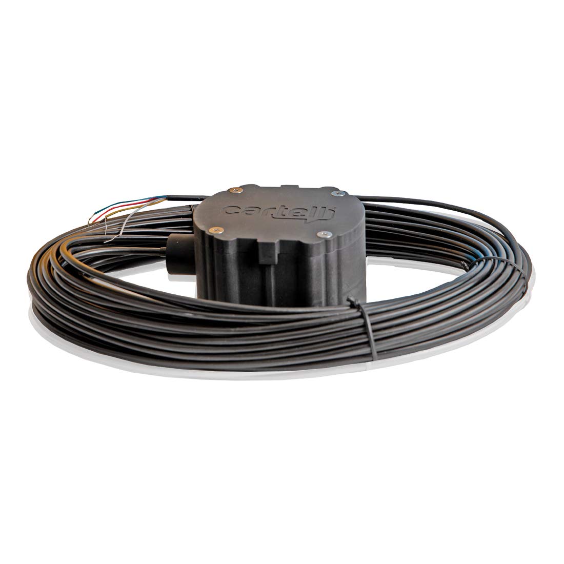
Image: The Cartell CP-4 control unit, showing its compact design and potential connection points. This unit is central to detecting vehicles and signaling the gate to open for free exit.
5. Operating Instructions
Once installed and configured, the Cartell CP-4 system operates automatically.
- When a vehicle approaches and drives over the inductive loop from the inside of the property, the CP-4 unit detects the vehicle's presence.
- Upon detection, the CP-4 activates its output relay, sending a signal to the gate operator.
- The gate operator receives this signal and initiates the gate opening sequence, allowing the vehicle to exit without manual intervention.
- The system will reset after the vehicle has cleared the loop and the gate has closed (if configured to do so by the gate operator).
Note: The CP-4 is a free exit system only. It does not control gate entry.
6. Maintenance
The Cartell CP-4 Free Exit System is designed for minimal maintenance. However, periodic checks can ensure long-term reliability.
- Visual Inspection: Periodically inspect the control unit for any signs of damage, moisture ingress, or loose connections.
- Loop Integrity: Check the loop sealant for cracks or deterioration. Repair any damage to prevent water from affecting the loop wire.
- Functionality Test: Regularly test the system by driving a vehicle over the loop to confirm it triggers the gate opening reliably.
- Cleanliness: Keep the control unit free from dust and debris. Use a soft, dry cloth for cleaning.
7. Troubleshooting
If you encounter issues with your CP-4 system, refer to the following common problems and solutions:
| Problem | Possible Cause | Solution |
|---|---|---|
| Gate does not open when vehicle is over loop. |
|
|
| Gate opens without a vehicle present (false detection). |
|
|
| Intermittent operation. |
|
|
If problems persist after attempting these solutions, contact technical support.
8. Specifications
| Model: | ASE-CP-3-100-5W (CP-4) |
| Brand: | FAS |
| Voltage: | 12 Volts (DC) |
| Material: | Copper (for associated wiring) |
| Item Weight: | 4 Pounds |
| Color: | Black |
| Number Of Wires: | 1 (referring to the main unit's connection points, not loop wire strands) |
| Number of Cable Strands: | Multiple strands (for associated wiring) |
9. Warranty Information
FAS products are manufactured to high-quality standards. This product is typically covered by a limited manufacturer's warranty against defects in materials and workmanship for a specified period from the date of purchase. Please retain your proof of purchase for warranty claims.
For specific warranty terms and conditions, please refer to the documentation provided with your purchase or contact FAS customer support.
10. Technical Support
If you require technical assistance, have questions about installation, or need to troubleshoot an issue not covered in this manual, please contact FAS customer support.
Contact Information:
- Website: www.fas.com (Placeholder, actual website may vary)
- Email: support@fas.com (Placeholder, actual email may vary)
- Phone: 1-800-XXX-XXXX (Placeholder, actual phone number may vary)
Please have your product model number (ASE-CP-3-100-5W) and date of purchase available when contacting support.
