1. Introduction
The PeakTech 4095 is a high-precision graphical True RMS bench multimeter designed for accurate electrical measurements in professional and hobbyist settings. This device features a 4-inch TFT color display, offering clear visualization of measurement data, including graphical trends. It supports a wide range of functions, including voltage, current, resistance, capacitance, frequency, and temperature measurements up to 1000 °C. With LAN, USB, and RS-232 interfaces, the PeakTech 4095 facilitates data logging and remote control, making it a versatile tool for various applications.
2. Safety Information
Please read all safety instructions carefully before operating the device.
- Always adhere to local and national safety regulations.
- This device is rated for CAT III 300V. Do not exceed the specified voltage and current limits for any input terminal.
- Ensure the multimeter is properly grounded before use, especially when connecting to mains power.
- Do not operate the device if it appears damaged or if the insulation is compromised.
- Use only the test leads and accessories supplied or recommended by PeakTech.
- Before changing functions or ranges, disconnect the test leads from the circuit under test.
- Exercise extreme caution when working with voltages above 30V AC RMS, 42V peak, or 60V DC, as these pose a shock hazard.
- Fuses must be replaced only with the specified type and rating (ceramic fuse).
3. Package Contents
Verify that all items are present and undamaged upon unpacking:
- PeakTech 4095 Bench Multimeter
- Test Leads
- Type K Thermocouple Wire Sensor
- Power Cord
- USB Cable
- User Manual (this document)
- Software CD (for DMM Tool and drivers)
4. Product Overview
4.1 Front Panel
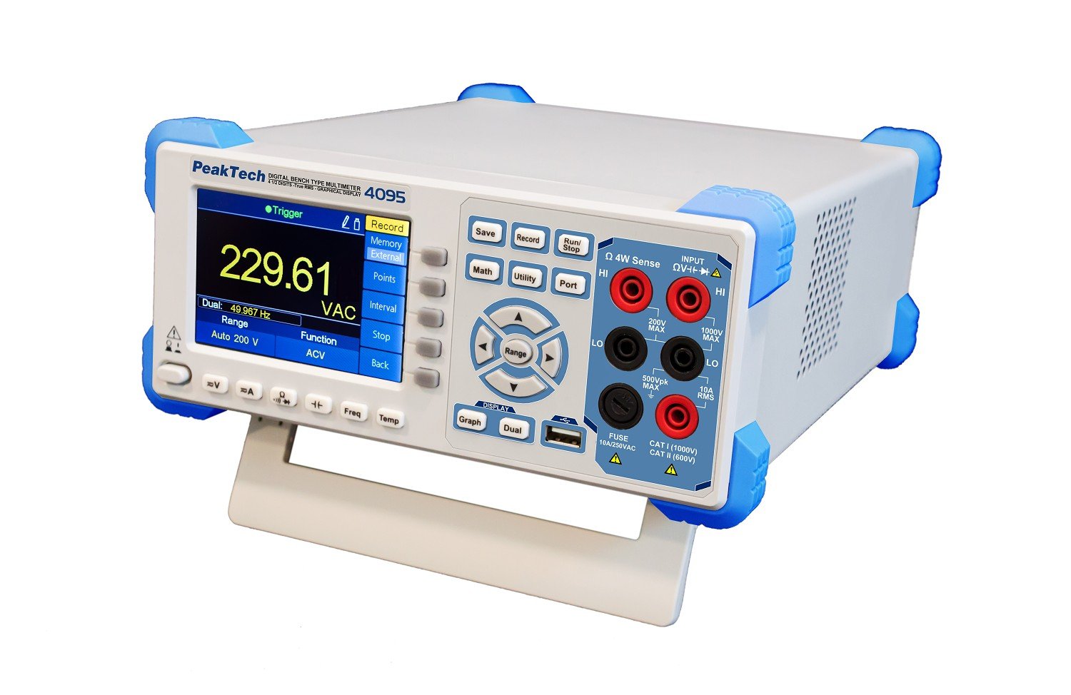
Figure 1: Front view of the PeakTech 4095 Bench Multimeter, showing the 4-inch TFT display, function buttons, navigation controls, and input terminals.
The front panel features the 4-inch TFT color display, which shows measurement values, graphs, and menu options. To the right of the display are the primary function buttons (Save, Record, Math, Utility, Port, Run/Stop) and navigation controls (Range, up/down/left/right arrows, Enter). Below the display are additional function buttons (Graph, Dual, V=, A=, Ω, Freq, Temp). On the far right are the input terminals for various measurements: HI/LO for voltage and resistance, 10A RMS for high current, and mA/µA for low current measurements. A USB host port is also located on the front for data storage.
4.2 Rear Panel

Figure 2: Rear view of the PeakTech 4095 Bench Multimeter, showing power input, LAN, USB, RS-232, and external trigger ports.
The rear panel includes the main power input socket, a line selector switch (110V/220V), LAN port for network connectivity, USB device port for PC connection, RS-232 serial port, and external trigger/AUX output ports. Ensure the line selector is set correctly for your region's mains voltage before connecting power.
5. Setup
5.1 Power Connection
- Before connecting the power cord, verify that the voltage selector switch on the rear panel is set to the correct mains voltage for your region (110V or 220V).
- Connect the supplied power cord to the power input socket on the rear panel of the multimeter.
- Plug the other end of the power cord into a grounded AC power outlet.
- Press the power button on the front panel to turn on the device. The TFT display will illuminate, and the device will perform a self-test.
5.2 Initial Configuration
Upon first power-on or after a factory reset, you may need to configure basic settings such as language, date, and time. Navigate through the 'Utility' menu using the front panel buttons to adjust these settings.
6. Operating Instructions
The PeakTech 4095 offers various measurement functions accessible via the front panel buttons. Always ensure test leads are connected to the correct input terminals for the desired measurement type.
6.1 Basic Measurements
- Voltage (V= / V~): Connect test leads to the HI and LO input terminals. Press the 'V=' button for DC voltage or 'V~' (often combined with V= or selected via a sub-menu) for AC voltage. The device supports True RMS measurements up to 100 kHz.
- Current (A= / A~): For current measurements, connect the test leads in series with the circuit. Use the 10A RMS input for high currents or mA/µA for lower currents. Select 'A=' for DC current or 'A~' for AC current.
- Resistance (Ω): Connect test leads to the HI and LO input terminals. Press the 'Ω' button. The device features a fast response time for resistance and continuity tests.
- Continuity Test: Select the resistance function and look for the continuity symbol. An audible tone indicates continuity.
- Diode Test: Select the diode test function (often combined with resistance). Connect the test leads to the diode to measure its forward voltage drop.
- Frequency (Freq): Connect the signal source to the HI and LO terminals. Press the 'Freq' button to measure the frequency of an AC signal.
- Temperature (Temp): Connect the Type K thermocouple wire sensor to the dedicated temperature input terminals (if available, or via adapter to HI/LO). Press the 'Temp' button. The device can measure temperatures up to 1000 °C (1372 °C maximum specified).
6.2 Graphical Display and Data Logging
The 4-inch TFT display allows for graphical representation of measurements, such as voltage trends over time. Use the 'Graph' button to switch to graphical mode. The 'Record' button initiates data logging, storing measurement points to internal memory or an external USB drive connected to the front panel port. The device can store up to 1 million measurement points.

Figure 3: Graphical display showing a trend of voltage measurements over time.
6.3 Advanced Functions
- Math Functions: The 'Math' button provides access to various mathematical operations on measurement data, such as MIN/MAX, AVG, dB, dBm.
- Utility Menu: The 'Utility' button allows access to system settings, calibration, display options, and interface configurations.
- Dual Display: The 'Dual' button enables simultaneous display of two different measurement parameters or a primary measurement with a secondary parameter (e.g., AC voltage and frequency).
7. Connectivity
The PeakTech 4095 offers multiple interfaces for data transfer and remote control.
- USB Interface: Connect the multimeter to a PC using the USB device port on the rear panel. This allows for data transfer and remote control via software. The front panel USB host port is for connecting USB storage devices for data logging.
- LAN Interface: Connect the multimeter to a network using an Ethernet cable. This enables remote control and data access over a local area network.
- RS-232 Interface: The serial RS-232 port on the rear panel provides another option for connecting the multimeter to a PC or other control systems.
For PC connectivity, install the 'DMM Tool' software and drivers from the supplied CD or PeakTech's website. While the software is designed for data acquisition and control, users have reported that specific versions may not be fully updated for the 4095 model's advanced features, particularly for direct PC control and processing of .csv recordings. For detailed instructions on using the software, refer to the software's documentation.
8. Maintenance
8.1 Cleaning
To clean the device, use a soft, damp cloth with a mild detergent. Do not use abrasive cleaners or solvents. Ensure the device is powered off and disconnected from all power sources and circuits before cleaning.
8.2 Fuse Replacement
If the current measurement function fails, the fuse may need replacement. Refer to the specifications for the correct ceramic fuse type and rating. Fuse replacement should only be performed by qualified personnel. Disconnect the device from all power sources and test leads before attempting to open the casing.
8.3 Calibration
The PeakTech 4095 is factory calibrated. For continued accuracy, periodic calibration by an authorized service center is recommended. Refer to the 'Utility' menu for calibration information.
9. Troubleshooting
- Device does not power on: Check the power cord connection and ensure the power outlet is functional. Verify the rear panel voltage selector switch is set correctly (110V/220V).
- No reading or 'OL' displayed: Ensure test leads are correctly connected to the appropriate input terminals and the circuit under test. Check if the measurement range is appropriate for the expected value; try a higher range if 'OL' (Overload) is displayed.
- Incorrect current reading: Check the fuse. Ensure the test leads are connected to the correct current input (10A or mA/µA) and in series with the circuit.
- Connectivity issues (LAN/USB/RS-232): Verify cable connections. Ensure correct drivers are installed on the PC. Check network settings for LAN connectivity.
- Display issues: If the display is dim or flickering, check power supply. If specific segments are missing, contact support.
10. Specifications
| Parameter | Value |
|---|---|
| Model Number | 4095 |
| Display | 4-inch TFT Color Display, 60,000 Counts |
| Measurement Type | True RMS Multimeter |
| AC Bandwidth | Up to 100 kHz |
| Data Logging | 1 Million Measurement Points |
| Interfaces | LAN, USB (Device & Host), RS-232 |
| Safety Rating | CAT III 300V, TÜV/GS, EN-61010-1 |
| Fuse Type | Ceramic Fuse |
| Temperature Measurement | Up to 1372 °C (Type K Thermocouple) |
| Power Source | Mains Powered (110V/220V selectable) |
| Product Dimensions (L x W x H) | 30 x 24 x 11 cm |
| Item Weight | 3 kg |
| Manufacturer | PeakTech |
| Country of Origin | China |
11. Warranty and Support
PeakTech products are manufactured with quality and reliability in mind. For warranty information, please refer to the warranty card included with your product or visit the official PeakTech website. In case of technical issues, questions, or service requests, please contact PeakTech customer support or your local distributor. Ensure you have your product model number (4095) and purchase details available when seeking support.


