
EPsolar VS1024BN
EPsolar ViewStar VS1024BN PWM Solar Charge Controller
Model: VS1024BN | Brand: EPsolar
Introduction
This manual provides detailed instructions for the installation, operation, and maintenance of the EPsolar ViewStar VS1024BN PWM Solar Charge Controller. This controller is designed for off-grid solar systems, such as street lighting, solar home systems, or small power stations. It features an LCD display, reliable battery charging, comprehensive electronic protections, and programmable parameters. Please read this manual thoroughly before installation and use to ensure proper function and safety.
Safety Information
Always observe the following safety precautions during installation and operation:
- Ensure all wiring is performed by qualified personnel and complies with local electrical codes.
- Connect the battery to the controller first, then the solar panel, and finally the load. Disconnect in the reverse order.
- Do not short-circuit the solar panel or battery terminals.
- Ensure adequate ventilation around the controller to prevent overheating.
- Avoid exposure to water or excessive humidity.
- The controller is designed for common negative grounding. Ensure all negative terminals are connected to a common ground.
- Wear appropriate personal protective equipment, including eye protection, when working with batteries.
Product Overview
The EPsolar ViewStar VS1024BN is a Pulse Width Modulation (PWM) solar charge controller. It automatically detects 12V or 24V system voltage and manages the charging process for various battery types.
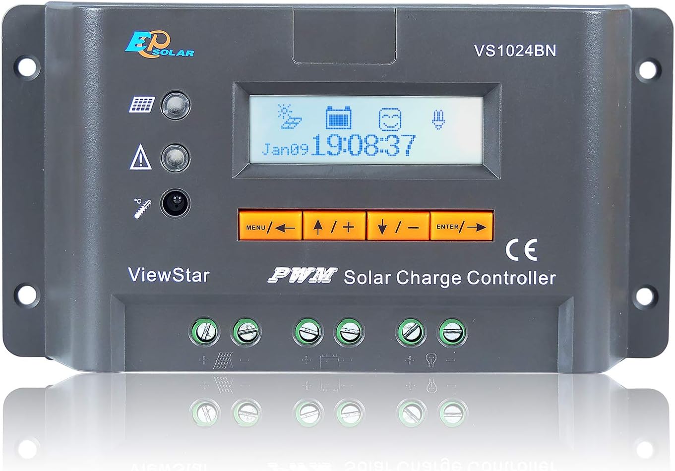
Figure 1: Front view of the EPsolar ViewStar VS1024BN Solar Charge Controller, showing the LCD display, control buttons, and terminal connections.
Components and Features

Figure 2: Labeled diagram of the VS1024BN controller's external components.
- Local temperature sensor: Measures the ambient temperature for temperature compensation.
- Fault LED indicator: Illuminates to indicate system faults or warnings.
- Charging LED indicator: Shows the charging status of the battery.
- Battery slot: Location for internal battery (if applicable, or for specific models).
- Liquid crystal display (LCD): Displays real-time system data and settings.
- Buttons: Four buttons for menu navigation and parameter adjustment.
- Communication port: RS485 port for PC monitoring software or remote meter connection.
- Load terminals: Connections for DC loads.
- Battery terminals: Connections for the battery bank.
- Solar module terminals: Connections for the solar panel array.
- Remote temperature sensor interface (optional): Port for an external temperature sensor (RTS300R47K3.81A).
Key Features:
- High-efficient Series PWM charging.
- Automatic 12V/24V system voltage recognition.
- Support for four battery types: Sealed, Gel, Flooded, and User-defined.
- Intelligent lighting and timer control for solar lighting systems.
- 12-bit A/D high-precision sampling for accurate data.
- MOSFET used as electronic switch.
- Full control parameters setting and modification, with diversified load control modes.
- Humanized browser interface with 4 buttons for easy operation.
- Temperature compensation for optimal charging.
- Energy statistics function.
- RS485 ports with MODBUS communication protocol.
- Optional PC monitoring software and remote meter (MT50) for real-time monitoring and parameter setting.
- Field upgradable firmware.
Electronic Protections:
- PV short circuit protection
- PV reverse polarity protection
- Battery overcharge protection
- Battery over discharge protection
- Battery reverse polarity protection
- Load overload protection
- Load short circuit protection
- Overheating protection (controller and battery)
Setup and Installation
Follow these steps for proper installation of the VS1024BN controller:
- Mounting: Choose a dry, well-ventilated location away from direct sunlight and heat sources. Ensure sufficient space around the controller for air circulation.
- Wiring Sequence:
- Connect the battery to the controller's battery terminals (9) first. Ensure correct polarity (+ to + and - to -). The controller will automatically detect the system voltage (12V or 24V).
- Connect the solar panel array to the controller's solar module terminals (10). Ensure correct polarity.
- Connect the DC load to the controller's load terminals (8). Ensure correct polarity.
- Grounding: The VS1024BN features common negative grounding. Ensure all negative terminals (battery, solar, load) are connected to a common ground point.
- Optional Remote Temperature Sensor: If using, connect the remote temperature sensor (RTS300R47K3.81A) to the interface (11). This improves charging accuracy by compensating for battery temperature fluctuations.
- Communication Port: For PC monitoring or remote meter (MT50) connection, use the RS485 communication port (7).

Figure 3: Typical solar system connection diagram with the VS1024BN controller, showing connections to solar panels, battery, load, and optional communication accessories.
Operating Instructions
LCD Display and Button Functions
The LCD (5) provides real-time system information. The four buttons (6) allow navigation through menus and adjustment of parameters.
- MENU button: Enters/exits the menu, or cycles through main display screens.
- UP/PLUS button: Navigates up in menus or increases parameter values.
- DOWN/MINUS button: Navigates down in menus or decreases parameter values.
- ENTER button: Confirms selection or enters editing mode for a parameter.
Battery Type Selection
It is crucial to select the correct battery type for optimal charging and battery longevity. Use the menu to select from Sealed, Gel, Flooded, or User-defined settings. Refer to your battery manufacturer's specifications for recommended charging voltages.
Load Control Modes
The controller offers diversified load control modes, including manual control, light control, and light control with timer. These settings are programmable via the LCD menu or through PC software/mobile app.
PC Software and Mobile App
The VS1024BN supports communication via its RS485 port. Optional PC monitoring software and a mobile application are available for real-time data monitoring, parameter setting, and energy statistics. This allows for more detailed system management.

Figure 4: Examples of the PC monitoring software interface and mobile application for EPsolar controllers, demonstrating data display and control options.
Maintenance
Regular maintenance ensures the longevity and optimal performance of your solar charge controller:
- Cleanliness: Keep the controller clean and free from dust and debris. Use a dry cloth for cleaning.
- Connections: Periodically check all wiring connections to ensure they are tight and free from corrosion. Loose connections can cause overheating and poor performance.
- Ventilation: Ensure that the ventilation openings are not blocked to allow for proper heat dissipation.
- Battery Health: Monitor battery voltage and health regularly. Ensure the battery type setting on the controller matches your battery.
- Firmware Updates: Check the manufacturer's website for any available firmware updates to ensure your controller has the latest features and bug fixes.
Troubleshooting
This section provides solutions to common issues you might encounter with the VS1024BN controller.
| Problem | Possible Cause | Solution |
|---|---|---|
| No display on LCD | Battery not connected or low voltage; reverse polarity. | Check battery connections and voltage. Ensure correct polarity. Charge battery if voltage is too low. |
| Battery not charging | Solar panel not connected; low solar voltage; PV reverse polarity; PV short circuit. | Check solar panel connections and ensure sufficient sunlight. Verify PV polarity. Check for PV short circuits. |
| Load not working | Load short circuit; load overload; battery low voltage; load control mode setting. | Check load wiring for short circuits. Reduce load power. Charge battery. Adjust load control mode settings. |
| Overheating warning | Insufficient ventilation; excessive ambient temperature; overloaded system. | Ensure proper airflow around the controller. Reduce load or improve ventilation. |
| Fault LED illuminated | Indicates a protection event (e.g., overcharge, over-discharge, short circuit). | Refer to the controller's display for specific fault codes and address the underlying issue. |
Specifications
Detailed technical specifications for the EPsolar ViewStar VS1024BN Solar Charge Controller:

Figure 5: Technical specifications table for the ViewStar series, including the VS1024BN model.
| Parameter | VS1024BN |
|---|---|
| Nominal System Voltage | 12V/24V Auto Work |
| Rated Charge Current | 10A |
| Rated Discharge Current | 10A |
| Battery Input Voltage Range | 9~32V |
| Equalize Charging Voltage* | Sealed: 14.6V, Gel: 14.8V, Flooded: 14.8V, User-defined: 9~17V |
| Boost Charging Voltage* | Sealed: 14.4V, Gel: 14.2V, Flooded: 14.6V, User-defined: 9~17V |
| Float Charging Voltage* | Sealed/Gel/Flooded: 13.8V, User-defined: 9~17V |
| Low Voltage Reconnect Voltage* | Sealed/Gel/Flooded: 12.6V, User-defined: 9~17V |
| Low Voltage Disconnect Voltage* | Sealed/Gel/Flooded: 11.1V, User-defined: 9~17V |
| Self-consumption | ≤15mA (12V); ≤10mA (24V) |
| Temperature Compensation Coefficient | -3mV/°C/2V |
| Grounding | Common Negative |
| Communication | RS485 / RJ45 interface |
| Overall Dimensions | 162 x 85 x 40 mm (6.38 x 3.35 x 1.57 inches) |
| Terminals | 12AWG (4mm²) |
| Net Weight | 0.3 kg (10.6 ounces) |
| Enclosure | IP30 |
*Technical data for 12V system at 25°C, twice in 24V system rate.
Warranty and Support
For warranty information and technical support, please refer to the official EPsolar website or contact your authorized dealer. Keep your purchase receipt as proof of purchase for any warranty claims.
Additional protection plans may be available for purchase to extend coverage beyond the standard manufacturer's warranty. Please check with your retailer for details on available protection plans.
Related documentsVS1024BN


Ask a question about this manual
Ask about setup, troubleshooting, compatibility, parts, safety, or missing instructions. Manuals+ will review the question and use this page’s manual context to help answer it.