
Semtech SRV05-4.TCT
SRV05-4.TCT TVS Diode Array User Manual
Model: SRV05-4.TCT
Brand: Semtech
Introduction
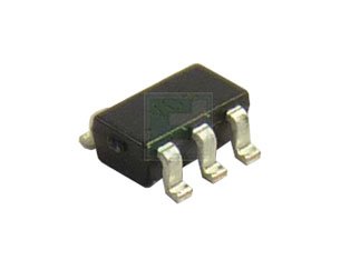
This manual provides essential information for the proper use and understanding of the Semtech SRV05-4.TCT TVS Diode Array. The SRV Series offers low capacitance ESD protection for high-speed data lines, making it suitable for a wide range of applications requiring robust circuit protection.
Key Features
- Number of Channels: 4
- Standoff Voltage: 5 V
- Capacitance: 3 pF
- Operating Temperature Range: -55 to +125 °C
- ESD Voltage Max: ±15 kV
- Leakage Current: 5 µA
- Storage Temperature Range: -55 to +150 °C
- Directional: Uni-Directional
- Clamping Voltage - Max: 17.5 V
- Breakdown Voltage - Max: 6 V
Specifications
| Attribute | Value |
|---|---|
| Item Model Number | SRV05-4.TCT |
| ASIN | B07346X1WN |
| Manufacturer | SEMTECH |
| Date First Available | June 22, 2017 |
Setup and Installation
The SRV05-4.TCT is a surface-mount device (SMD) designed for integration onto printed circuit boards (PCBs). Proper installation requires adherence to standard SMD soldering practices.
- Component Handling: Always handle the device in an ESD-safe environment to prevent damage from electrostatic discharge. Use appropriate grounding straps and mats.
- Soldering: Follow recommended soldering profiles for SOT-23-6L packages. Ensure correct pad alignment and sufficient solder paste application for reflow soldering. Avoid excessive heat or prolonged exposure to high temperatures.
- Placement: Place the component accurately on the designated PCB pads. Verify correct orientation as per the datasheet's pinout diagram.
- Post-Soldering Inspection: Visually inspect solder joints for proper formation, absence of bridges, and good wetting.
It is recommended that installation be performed by qualified personnel with experience in electronic assembly.
Operating Principles
The SRV05-4.TCT is a Transient Voltage Suppressor (TVS) diode array. TVS diodes are designed to protect sensitive electronic components from electrostatic discharge (ESD) and other transient voltage events such as electrical fast transients (EFT) and lightning surges. When a transient voltage exceeding the device's breakdown voltage occurs, the TVS diode rapidly switches into a low impedance state, diverting the harmful current away from the protected circuit and clamping the voltage to a safe level. The low capacitance of the SRV05-4.TCT ensures minimal signal degradation on high-speed data lines.
Maintenance
The SRV05-4.TCT is a solid-state, passive electronic component and typically requires no routine maintenance once properly installed. Its robust design ensures long-term reliability under specified operating conditions.
- Environmental Conditions: Ensure the operating environment remains within the specified temperature and humidity ranges to prevent premature component degradation.
- Physical Inspection: Periodically, if accessible, inspect the component and surrounding PCB area for any signs of physical damage, discoloration, or solder joint issues, especially after any system-level transient events.
Troubleshooting
As a protection device, the SRV05-4.TCT itself is not typically 'troubleshot' in the same way an active component might be. Its primary function is to sacrifice itself, if necessary, to protect the downstream circuitry from severe overvoltage events.
- Protected Circuit Failure: If the circuit protected by the SRV05-4.TCT fails, first verify the integrity of the SRV05-4.TCT. A damaged or shorted TVS diode may indicate that it successfully absorbed an overstress event.
- Component Damage: Visible signs of damage (e.g., charring, cracking) on the SRV05-4.TCT suggest it has experienced a transient event exceeding its maximum ratings. In such cases, the component should be replaced.
- Incorrect Operation: If the protected circuit is still experiencing issues despite the presence of the SRV05-4.TCT, ensure that the component was correctly installed, its specifications (e.g., clamping voltage, power rating) are appropriate for the expected transients, and that all protected lines are routed through the device.
Warranty and Support
For detailed warranty information, technical support, and access to the latest datasheets and application notes for the SRV05-4.TCT, please refer to the official Semtech website or contact your authorized Semtech distributor. Specific warranty terms are subject to the point of purchase and regional regulations.
This manual provides general guidance. Always consult the official product datasheet for the most accurate and up-to-date technical specifications and application guidelines.
Related documentsSRV05-4.TCT


Ask a question about this manual
Ask about setup, troubleshooting, compatibility, parts, safety, or missing instructions. Manuals+ will review the question and use this page’s manual context to help answer it.