1. Introduction
This manual provides detailed instructions for the installation, operation, and maintenance of the Inkbird ITC-100VH PID Temperature Controller. The ITC-100VH is designed for precise temperature control in various industrial and scientific applications, offering both PID and ON/OFF control modes with a self-adjusting function for long-term stability.
2. Safety Information
- Ensure the power supply voltage matches the controller's specifications (AC 100~240V).
- All wiring should be performed by a qualified electrician to prevent electric shock or damage to the device.
- Do not operate the controller in environments with excessive humidity, dust, corrosive gases, or strong vibrations.
- Disconnect power before performing any maintenance or wiring changes.
- This device is not intended for life-support systems or other applications where device malfunction could result in personal injury or property damage.
3. Product Overview
The Inkbird ITC-100VH is a compact and versatile PID temperature controller featuring a dual digital display for Process Value (PV) and Set Value (SV). It supports multiple temperature sensor types and offers an SSR output for precise control and a relay alarm output for safety or process indication.
Key Features:
- PID and ON/OFF Control Mode with high standard self-adjust function.
- Compatible with multiple temperature sensors like K, S, Wre, T, E, J, B, N, CU50, PT100.
- Display and control accuracy of ±0.2%FS, 0.1°C (<1000°C), 1°C (≥1000°C).
- Intelligent control ensures long-term stability.
- Suitable for devices without water circulation, such as ovens.
Components:
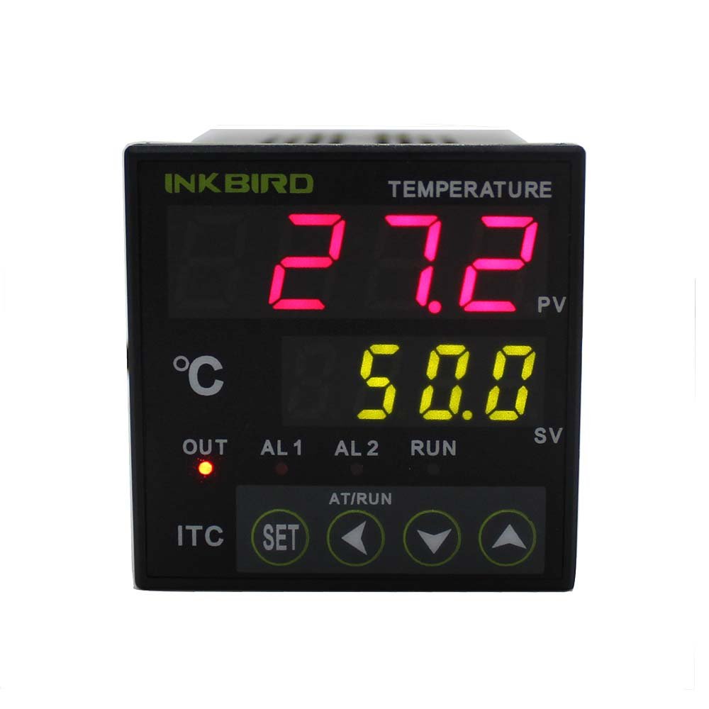
Figure 3.1: Front view of the Inkbird ITC-100VH PID Temperature Controller, showing the dual digital display for PV and SV, and control buttons.
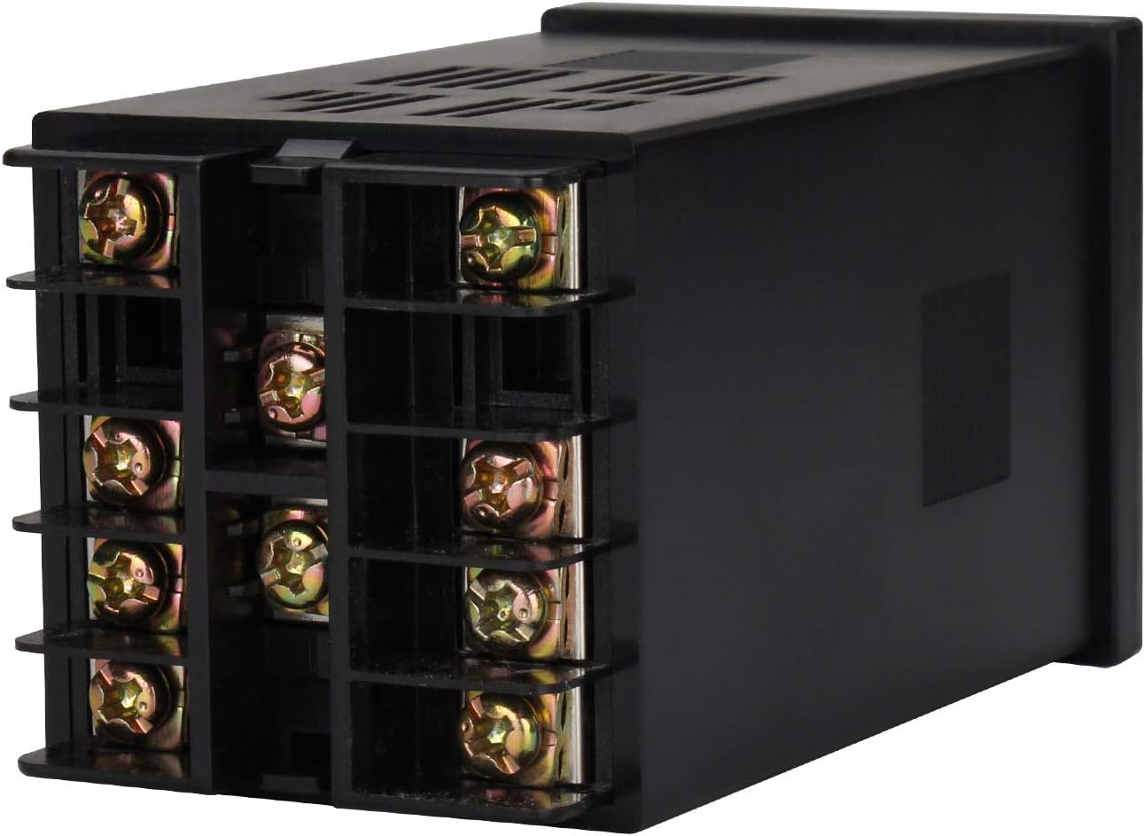
Figure 3.2: Rear view of the controller, illustrating the screw terminals for power, sensor input, and output connections.

Figure 3.3: Model number breakdown for the ITC-100 series, indicating power supply and output configurations. The ITC-100VH model features AC100-240V power, one SSR output, and one relay alarm output.
4. Specifications
| Specification | Value |
|---|---|
| Model Number | ITC-100VH |
| Front Panel Dimension | DIN 48mm(W) x 48mm(L) |
| Power Supply Voltage | AC 100~240V 50/60Hz |
| Operating Voltage Range | 85~110% Rated voltage |
| Power Consumption | 5VA (approx) |
| PV Character Display | 4 digital 9.9mm height Red LED Letters |
| SV Character Display | 4 digital 8mm height Green LED Letters |
| Display Accuracy | ±0.2%FS, 0.1°C (<1000°C), 1°C (≥1000°C) |
| Period of Sampling | 0.5S |
| Temperature Compensation | 0~50°C |
| Main Output | Voltage Pulses Output (DC 12V, 30mA) |
| Alarm Output | AC250V 3A (Resistive load) ON/NC |
| Life Expectancy of Relay | Mechanical ≥10,000,000 operations, Electrical ≥10,000,000 operations |
| Weight | 140g (approx) |
| Environmental Conditions | -10~55°C, RH 35~85% Humidity (no icy or condensation) |
| Storage Temperature | -25~65°C (no icy or condensation) |
| Data Storage | 10 years |
| Cutout size | 45x45mm |
| Mounting Method | Flush mounting and screw terminals |
5. Setup and Installation
The ITC-100VH is designed for flush mounting into a panel. Ensure the cutout size is 45x45mm. Connect the power supply, temperature sensor, and output devices to the appropriate screw terminals on the rear of the controller.
Wiring Diagram:
Refer to the diagram on the product label or in Figure 3.3 for correct wiring connections. The ITC-100VH model has an SSR output and a relay alarm output. Ensure all connections are secure and insulated.
Installation Process:
- Prepare a panel cutout of 45x45mm.
- Insert the controller into the cutout from the front.
- Secure the controller using the provided mounting brackets from the rear.
- Connect the power supply (AC 100-240V) to the designated terminals.
- Connect your chosen temperature sensor (e.g., K-type thermocouple, PT100 RTD) to the sensor input terminals. Ensure correct polarity for thermocouples.
- Connect your Solid State Relay (SSR) to the SSR output terminals (DC 12V, 30mA).
- Connect your alarm device to the relay alarm output terminals (AC250V 3A).
- Double-check all connections before applying power.
Visual Installation Guide:
Video 5.1: This video illustrates the assembly and wiring of a temperature control box utilizing a PID temperature controller, showcasing the integration of components. While it features a different model, the general principles of installation and wiring are applicable.
Video 5.2: This video demonstrates the general installation process for a PID temperature controller, including mounting and basic wiring connections. It provides a visual aid for understanding the physical setup.
6. Operating Instructions
The Inkbird ITC-100VH features a user-friendly interface for setting and monitoring temperature. The upper display (PV) shows the current process temperature, while the lower display (SV) shows the set target temperature.
Basic Operation:
- Power On: Once wired correctly, apply power to the controller. The displays will light up.
- Setting Temperature (SV): Press the SET button to enter the setting mode. Use the arrow keys (▲ / ▼) to adjust the Set Value (SV). Press SET again to confirm and exit.
- Monitoring: In normal operating mode, the PV display shows the actual temperature, and the SV display shows your target temperature.
- Output Indication: The 'OUT' indicator will illuminate when the control output is active. The 'AL1' and 'AL2' indicators will light up when the respective alarms are triggered.
Advanced Settings (Parameter Configuration):
The controller has various parameters for fine-tuning its operation, including sensor type, control mode (PID/ON-OFF), alarm settings, and self-tuning. Accessing and modifying these parameters typically involves pressing and holding the SET button for several seconds to enter the parameter menu. Consult the full technical manual for a complete list of parameters and their functions.
- Sensor Type: Ensure the controller is configured for the correct sensor type (e.g., K, PT100) to ensure accurate readings.
- PID Auto-Tuning: The self-adjust function (AT/RUN button) can automatically calculate optimal PID parameters for your specific heating/cooling system, improving control accuracy and stability.
- Alarm Settings: Configure alarm thresholds and modes (e.g., high limit, low limit) for the relay alarm output.
7. Maintenance
Regular maintenance ensures the longevity and accurate operation of your Inkbird ITC-100VH PID Temperature Controller.
- Cleaning: Periodically clean the front panel with a soft, dry cloth. Do not use abrasive cleaners or solvents.
- Connection Checks: Regularly inspect all wiring connections for tightness and signs of corrosion or damage. Loose connections can lead to inaccurate readings or intermittent operation.
- Environmental Conditions: Ensure the operating environment remains within the specified temperature and humidity ranges to prevent damage.
- Sensor Inspection: Check the temperature sensor for physical damage or degradation, which can affect measurement accuracy.
8. Troubleshooting
If you encounter issues with your ITC-100VH controller, refer to the following common troubleshooting steps:
| Problem | Possible Cause | Solution |
|---|---|---|
| No display/Power off | No power supply; Incorrect wiring; Blown fuse | Check power connections; Verify wiring against diagram; Replace fuse if necessary. |
| Inaccurate temperature reading | Incorrect sensor type setting; Faulty sensor; Loose sensor connection; Temperature offset needed | Verify sensor type in settings; Check sensor for damage; Secure sensor wiring; Adjust temperature offset if a consistent deviation is observed. |
| Controller not heating/cooling | Output wiring incorrect; Faulty SSR/relay; Set value not reached; PID parameters incorrect | Check output wiring; Test SSR/relay functionality; Adjust SV; Perform PID auto-tuning. |
| Alarm not triggering | Alarm settings incorrect; Alarm wiring incorrect; Faulty alarm device | Review alarm parameters; Check alarm output wiring; Test alarm device. |
If the problem persists after attempting these solutions, please contact Inkbird customer support.
9. Warranty and Support
Warranty:
The Inkbird ITC-100VH PID Temperature Controller comes with a 1-year warranty from the date of purchase. This warranty covers defects in materials and workmanship under normal use. It does not cover damage caused by misuse, unauthorized modification, accident, or improper installation.
Customer Support:
For technical assistance, troubleshooting, or warranty claims, please contact Inkbird customer support through their official website or the retailer where the product was purchased. Please have your model number (ITC-100VH) and purchase information ready when contacting support.


