
1. Introduction
This manual provides detailed instructions for the WINGONEER Voltage to Current Module, model LC-V2A. This module is designed to convert a 0-5V voltage input signal into a 0-20mA current output signal. Its compact size and robust features make it suitable for various industrial and hobbyist applications requiring voltage-to-current conversion.
2. Product Features
- MCU Embedded Technology: Utilizes advanced microcontroller technology for stable and accurate conversion.
- Standard Signal Conversion: Converts industry-standard 0-5V voltage input to 0-20mA current output.
- Linear Output: Provides a linear relationship between input voltage and output current.
- High Drive Capability: Maximum drive capability of 15mA.
- Direct AD Converter Connection: Output signal can be directly connected to an AD converter for data acquisition.
- Easy Operation: Features a fine-tuning potentiometer for precise calibration.
- Compact Design: Small and portable module, convenient for integration into various systems.
3. Technical Specifications
| Parameter | Value |
|---|---|
| Operating Voltage | DC 10V - 30V |
| Input Voltage Range | 0-5V |
| Output Current Range | 0-20mA |
| Conversion Type | Voltage to Current |
| Drive Capability | Max 15mA |
| Dimensions (Approx.) | 8.9 x 6.6 x 0.8 cm |
| Weight (Approx.) | 18 g |
4. Setup and Wiring
Proper wiring is crucial for the correct operation and longevity of the module. Refer to the connection diagram and pin descriptions below.
4.1 Connection Diagram
The image below illustrates the terminal layout for the WINGONEER Voltage to Current Module.
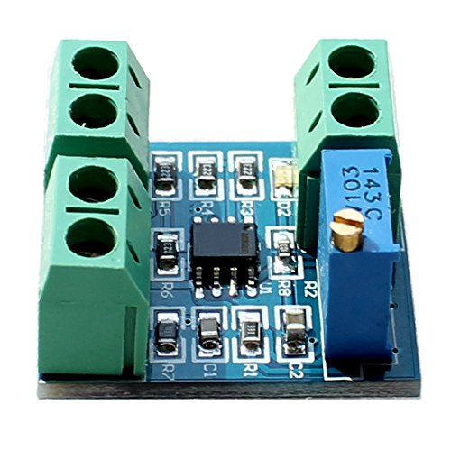
Figure 1: Top view of the WINGONEER Voltage to Current Module, highlighting the input/output terminals and the fine-tuning potentiometer.
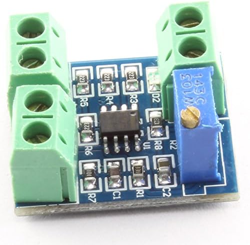
Figure 2: Angled view of the module, providing a perspective of its compact form factor and terminal blocks.
4.2 Pin Descriptions
- VCC: Power supply input (DC 10V - 30V).
- GND (Power): Ground for the power supply.
- VIN: Voltage input signal (0-5V).
- GND (Input): Ground for the input voltage signal.
- OUT: Current output signal (0-20mA).
- GND (Output): Ground for the output current signal.
4.3 Wiring Precautions
- Ensure that the operating voltage (VCC) and its corresponding ground (GND) are connected correctly. Avoid reverse connection to prevent damage to the board and its components.
- Connect the input voltage signal (VIN) within the specified 0-5V range.
- Connect the output (OUT) to your receiving device, ensuring proper polarity.
5. Operating Instructions
Once the module is correctly wired and powered, it will begin converting the input voltage to a corresponding current output.
- Apply Input Voltage: Provide a voltage signal between 0V and 5V to the VIN terminal.
- Observe Output Current: The module will generate a corresponding current output between 0mA and 20mA at the OUT terminal.
- Fine-Tuning Calibration: If precise calibration is required, use the onboard potentiometer to fine-tune the relationship between the input voltage and the output current. Turn the potentiometer gently with a small screwdriver to adjust the output.
6. Maintenance
The WINGONEER Voltage to Current Module is designed for reliable operation with minimal maintenance. Follow these general guidelines:
- Keep the module clean and free from dust and debris.
- Avoid exposing the module to extreme temperatures, humidity, or corrosive environments.
- Ensure all connections remain secure. Periodically check wiring for any signs of wear or damage.
- Do not attempt to open or modify the module beyond the specified adjustments, as this may void any potential warranty and could cause damage.
7. Troubleshooting
If you encounter issues with the module, consider the following troubleshooting steps:
- No Output/Incorrect Output:
- Verify that the power supply (VCC) is within the 10V-30V range and correctly connected.
- Check all wiring connections for proper polarity and secure contact. Ensure no reverse connections are made.
- Confirm that the input voltage (VIN) is within the 0-5V range.
- Use a multimeter to measure the input voltage and output current to confirm expected values.
- Adjust the fine-tuning potentiometer to see if it affects the output.
- Module Not Powering On:
- Ensure the power supply is active and providing the correct voltage.
- Check for any short circuits or loose connections in the power input.
If the problem persists after these steps, contact customer support for further assistance.
8. Package Contents
The package includes:
- 1x WINGONEER Voltage to Current Module (0-5V to 0-20mA)