Introduction
This manual provides essential information for the installation, operation, and maintenance of the AMETEK PANALARM Alert Panel, Model 204L1N4T1C3E. This device is designed to provide visual and audible alerts for various industrial conditions, ensuring timely notification of system statuses or anomalies.
The 204L1N4T1C3E is a 24VDC, 1.0A alert panel, engineered for reliability and clear indication in critical environments.
Safety Information
WARNING: Read all instructions carefully before installation and operation. Failure to follow these instructions may result in equipment damage, personal injury, or death.
- Ensure power is disconnected before performing any installation, maintenance, or troubleshooting.
- Installation and servicing should only be performed by qualified personnel.
- Verify correct voltage and current ratings before connecting the panel to a power source. The panel operates on 24VDC.
- Protect the panel from excessive moisture, dust, and extreme temperatures.
- Do not operate the panel if it appears damaged.
Setup and Installation
The AMETEK PANALARM Alert Panel is designed for panel mounting. Follow these steps for proper installation:
- Panel Preparation: Cut an appropriate opening in the control panel according to the dimensions provided in the specifications section. Ensure sufficient clearance for wiring and ventilation.
- Mounting: Insert the alert panel into the prepared opening. Secure it using the provided mounting hardware. Ensure the panel is flush and stable.
- Wiring:
- Power Connection: Connect the 24VDC power supply to the designated terminals. Observe correct polarity (+ and -). The panel requires 1.0A.
- Input Signals: Connect the alarm input signals to the corresponding terminals. Refer to the wiring diagram (if available with your specific unit) for detailed terminal assignments.
- Output Signals (if applicable): If the panel includes relay outputs for external devices, connect them as required.
- Verification: After all connections are made, double-check all wiring for correctness and security before applying power.

Figure 1: Side view of the alert panel, displaying the model number 204L1N4T1C3E, 24 Volts DC, and 1.0 Amps rating.
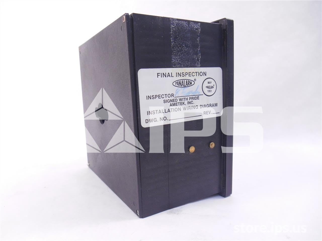
Figure 2: Rear view of the alert panel, showing the "Final Inspection" label and mounting points.
Operating Instructions
The AMETEK PANALARM Alert Panel provides clear visual and, potentially, audible indications of various system states. Its operation is largely automatic, responding to input signals.
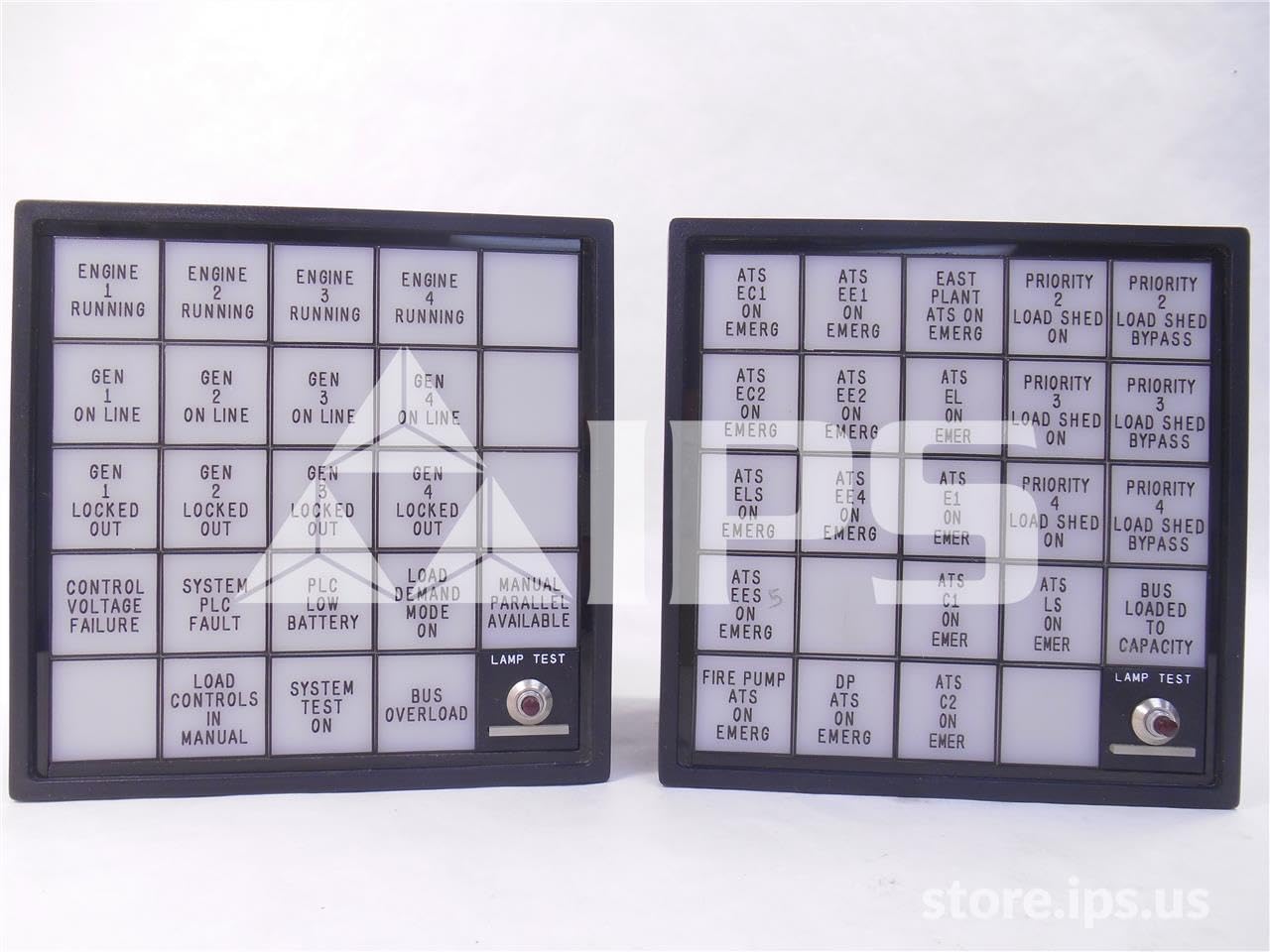
Figure 3: Front view of two alert panels, illustrating various indicator labels such as "ENGINE RUNNING", "GEN ON LINE", "LOCKED OUT", "LOAD SHED", and "PRIORITY". Each panel includes a "LAMP TEST" button.
- Indicator Lights: Each segment of the panel corresponds to a specific system status or alarm condition. When an associated condition is met, the corresponding light will illuminate.
- Audible Alarm (if equipped): If the panel includes an audible alarm, it will sound when an alarm condition is detected.
- Acknowledge Button (if equipped): Some models may have an acknowledge button to silence the audible alarm while the visual indication remains active until the condition clears.
- Lamp Test Button: Pressing the "LAMP TEST" button (visible on the front of the panel) will illuminate all indicator lights to confirm their functionality. This is a crucial step for routine checks.
Familiarize yourself with the specific labels on your panel to understand what each indicator signifies in your system.
Maintenance
The AMETEK PANALARM Alert Panel is designed for minimal maintenance. Regular checks ensure its continued reliable operation.
- Routine Inspection: Periodically inspect the panel for any signs of physical damage, loose connections, or excessive dust accumulation.
- Cleaning: Clean the front face of the panel with a soft, dry, or slightly damp cloth. Do not use abrasive cleaners or solvents. Ensure no liquid enters the panel.
- Lamp Test: Perform the "LAMP TEST" function regularly (e.g., monthly) to confirm all indicator lights are operational. Replace any non-functioning lamps as per manufacturer's guidelines (if user-replaceable).
- Connection Check: Annually, or as part of your system's preventative maintenance schedule, verify that all wiring connections are secure and free from corrosion. Ensure power is disconnected before checking connections.
Troubleshooting
This section provides solutions to common issues you might encounter with your alert panel.
| Problem | Possible Cause | Solution |
|---|---|---|
| Panel does not power on. | No power supply; Incorrect wiring; Blown fuse (external to panel). | Check 24VDC power supply connection and voltage. Verify wiring polarity. Check external fuses in the power circuit. |
| Individual indicator light not illuminating during lamp test. | Faulty lamp/LED; Internal wiring issue. | If lamps are replaceable, replace the faulty lamp. If not, or if issue persists, contact qualified service personnel. |
| Indicator light remains on/off incorrectly. | Incorrect input signal; Faulty input wiring; Internal panel fault. | Verify the status of the input signal. Check wiring from the signal source to the panel. If signals are correct and wiring is good, the panel may require service. |
| Audible alarm not sounding (if equipped). | Faulty alarm component; Disabled alarm. | Check if the alarm is enabled. If not, contact service personnel. |
For issues not listed here or if troubleshooting steps do not resolve the problem, contact AMETEK technical support or a qualified service technician.
Specifications
| Attribute | Value |
|---|---|
| Model Number | 204L1N4T1C3E |
| Manufacturer | AMETEK |
| Input Voltage | 24 VDC |
| Current Draw | 1.0 A |
| Product Dimensions (L x W x H) | 8 x 8 x 8 inches |
| Weight | 2 Pounds |
| ASIN | B06XP65GHF |
| First Available Date | March 16, 2017 |
Warranty and Support
For specific warranty information regarding your AMETEK PANALARM Alert Panel, Model 204L1N4T1C3E, please refer to the documentation provided with your purchase or contact AMETEK directly. Warranty terms typically cover defects in materials and workmanship under normal use.
Technical Support: For technical assistance, troubleshooting beyond this manual, or service inquiries, please contact AMETEK customer support. Have your model number (204L1N4T1C3E) and serial number (if applicable) ready when contacting support.
Manufacturer: AMETEK
For the most current contact information, please visit the official AMETEK website.


