
ABB FS450R17KE3/AGDR-71C
ABB FS450R17KE3/AGDR-71C IGBT Module and Drive User Manual
Model: FS450R17KE3/AGDR-71C
1. Introduction
This manual provides essential information for the safe and effective use of the ABB FS450R17KE3/AGDR-71C IGBT Module and Drive. This high-performance component is designed for industrial electrical applications, integrating an Insulated Gate Bipolar Transistor (IGBT) module with its associated drive circuitry. Proper installation, operation, and maintenance are crucial for optimal performance and longevity.
The ABB FS450R17KE3/AGDR-71C is a critical component in power electronics, offering efficient power conversion and control. It is imperative that all procedures outlined in this manual are followed by qualified personnel only.
2. Safety Information
WARNING: Risk of Electric Shock and Component Damage!
- All installation, maintenance, and troubleshooting procedures must be performed by qualified and authorized personnel only.
- Ensure all power sources are disconnected and locked out before performing any work on the module or connected systems.
- Observe proper Electrostatic Discharge (ESD) precautions when handling the module. Wear anti-static wrist straps and work on an ESD-safe surface.
- Do not touch live electrical parts. Capacitors may retain charge even after power is disconnected.
- Verify correct wiring and connections before applying power. Incorrect wiring can lead to severe damage or injury.
- The module can become hot during operation. Allow sufficient cooling time before handling.
Failure to follow these safety instructions can result in serious injury, death, or severe damage to equipment.
3. Setup and Installation
Careful handling and correct installation are vital for the performance and longevity of the IGBT module. The module is sensitive to electrostatic discharge (ESD) and physical shock.
3.1 Unpacking and Inspection
Upon receiving the ABB FS450R17KE3/AGDR-71C, carefully inspect the packaging for any signs of damage. If damage is observed, document it and contact your supplier immediately.
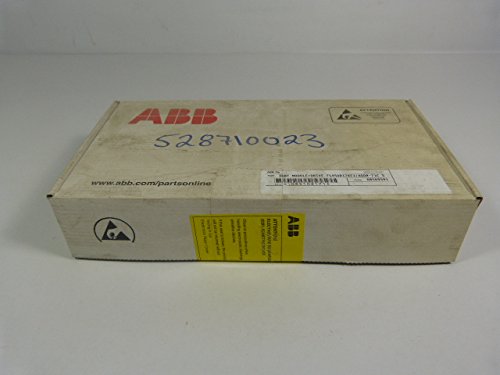
Figure 3.1: The ABB FS450R17KE3/AGDR-71C IGBT Module and Drive as received in its original, sealed packaging. The packaging includes ABB branding and product identification labels.
Carefully open the packaging and remove the module and its accessories. Verify that all components are present and undamaged. The package typically includes the IGBT module, mounting hardware (screws), and thermal paste.

Figure 3.2: Contents of the ABB FS450R17KE3/AGDR-71C package. Shown are the IGBT module, a bag of mounting screws, three tubes of thermal paste, and accompanying documentation.
Note the product identification details on the packaging label, such as the type "IGBT MODULE+DRIVE FS450R17KE3/AGDR-71C S" and the serial number "1085102171".
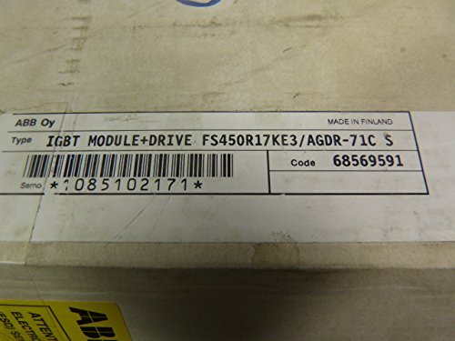
Figure 3.3: Close-up view of the product label on the ABB FS450R17KE3/AGDR-71C packaging. The label clearly indicates the product type, model number, and a unique serial number (1085102171).
3.2 Mounting the Module
The IGBT module must be mounted on a suitable heatsink to ensure proper thermal management. Apply a thin, even layer of the provided thermal paste to the baseplate of the module before mounting. This ensures efficient heat transfer.

Figure 3.4: Top view of the ABB FS450R17KE3/AGDR-71C IGBT Module. This image highlights the intricate circuitry, power terminals, and control connections necessary for its operation within an industrial system.
Secure the module to the heatsink using the provided mounting screws. Tighten screws evenly to ensure uniform pressure and optimal thermal contact. Refer to the module's technical datasheet for specific torque recommendations.
3.3 Electrical Connections
Connect the power terminals (DC link, AC output) and control signals according to the system's wiring diagram and the module's datasheet. Ensure all connections are secure and properly insulated. Pay close attention to polarity and phase sequencing.
- Power Terminals: Connect high-current cables to the main power terminals.
- Gate Drive Connections: Connect the control signals from the system's controller to the gate drive inputs.
- Auxiliary Power: Provide necessary auxiliary power for the gate drive circuitry.
Before applying power, double-check all connections for correctness and security. Incorrect wiring can lead to immediate damage to the module or connected equipment.
4. Operating Instructions
The ABB FS450R17KE3/AGDR-71C IGBT Module and Drive is designed for integration into larger power electronic systems. Its operation is typically controlled by an external control unit (e.g., a microcontroller or DSP) that provides the necessary gate drive signals.
- Power-Up Sequence: Follow the recommended power-up sequence as specified in the system's design documentation. Typically, auxiliary power for the gate drive should be applied before the main DC link voltage.
- Gate Signals: Apply appropriate PWM (Pulse Width Modulation) signals to the gate inputs to control the switching of the IGBTs. Ensure the gate voltage levels and pulse widths are within the specified limits.
- Monitoring: Monitor key operating parameters such as current, voltage, and temperature to ensure the module operates within its safe operating area (SOA).
- Shutdown Procedure: Implement a controlled shutdown sequence, typically by disabling gate signals before disconnecting main power.
Refer to the detailed technical datasheet for specific electrical characteristics, timing diagrams, and application notes relevant to your system design.
5. Maintenance
Regular maintenance helps ensure the long-term reliability and performance of the IGBT module. Always disconnect all power and observe safety precautions before performing any maintenance.
- Cleaning: Periodically inspect the module and heatsink for dust and debris accumulation. Clean with compressed air or a soft, dry brush. Do not use solvents that could damage components.
- Thermal Paste Inspection: Over time, thermal paste can degrade. If the module is removed for any reason, it is recommended to clean off old thermal paste and reapply a fresh layer upon reinstallation.
- Connection Checks: Periodically check all electrical connections for tightness and signs of corrosion or overheating. Re-tighten if necessary.
- Environmental Conditions: Ensure the operating environment remains within the specified temperature and humidity ranges to prevent premature aging or failure.
6. Troubleshooting
This section provides general guidance for common issues. For complex problems, consult the detailed technical documentation or contact ABB technical support.
| Problem | Possible Cause | Solution |
|---|---|---|
| Module not switching / No output |
|
|
| Overheating |
|
|
| Unexpected shutdown |
|
|
7. Specifications
The following are key specifications for the ABB FS450R17KE3/AGDR-71C IGBT Module and Drive. For complete technical details, refer to the official ABB datasheet for this model.
- Model: FS450R17KE3/AGDR-71C
- Manufacturer: ABB
- Product Dimensions: 20.08 x 14.17 x 14.17 inches
- Weight: Approximately 6.61 Pounds
- First Available: March 1, 2017
- Type: IGBT Module and Drive
- ASIN: B06XCH1KVX
Note: These specifications are subject to change without notice. Always refer to the latest official documentation from ABB for critical design and application information.
8. Warranty and Support
Warranty terms for the ABB FS450R17KE3/AGDR-71C IGBT Module and Drive are provided by ABB and are typically dependent on the point of purchase and regional regulations. Please retain your proof of purchase for warranty claims.
For technical support, detailed datasheets, application notes, or warranty inquiries, please contact ABB directly or visit their official website. You can find more information about ABB products and support at the ABB Store on Amazon or their corporate website.
When contacting support, please have your product model (FS450R17KE3/AGDR-71C) and serial number (e.g., 1085102171, as seen on the product label) ready.
Related documentsFS450R17KE3/AGDR-71C

Ask a question about this manual
Ask about setup, troubleshooting, compatibility, parts, safety, or missing instructions. Manuals+ will review the question and use this page’s manual context to help answer it.