
1. Introduction
This manual provides essential information for the installation, operation, maintenance, and troubleshooting of your SCITOO Starter, model 4730920-M030SM. This starter is designed for specific OMC, Johnson, and Evinrude outboard marine engines. Please read this manual thoroughly before attempting any procedures to ensure proper function and safety.
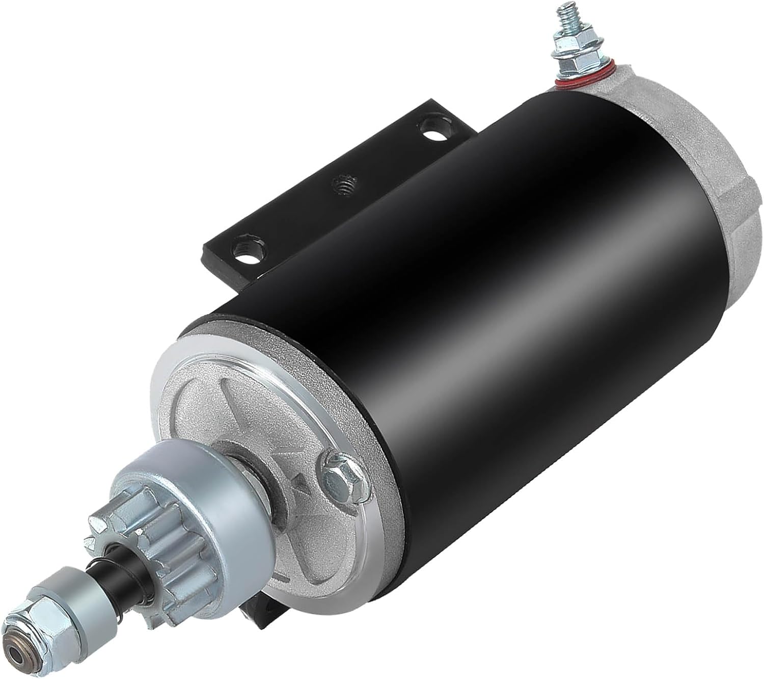
Image 1.1: The SCITOO Starter Motor, model 4730920-M030SM. This image displays the overall design and components of the starter unit.
2. Compatibility
The SCITOO Starter, model 4730920-M030SM, is compatible with various OMC, Johnson, and Evinrude outboard engine models. Please verify your engine's specifications against the following compatibility lists and reference numbers before installation.
2.1. Evinrude Models

Image 2.1: A table detailing compatible Evinrude outboard engine models by year, make, model, and engine type.
This starter is compatible with various Evinrude models, including but not limited to those listed in the image above, typically 120, 130, and 140 HP engines from 1985 to 1993. Specific models include E120TLCCA, E120TLCDC, E120TLCEM, E120TLCOS, E120TLCUR, E120TLEIE, E120TLEND, E120TLESB, E120TLETF, E120TLETS, E120TXATF, E120TXATS, E120TXCCA, E120TXCDC, E120TXCEM, E120TXCOS, E120TXCUR.
2.2. Johnson Models

Image 2.2: A table detailing compatible Johnson outboard engine models by year, make, model, and engine type.
This starter is also compatible with various Johnson models, including those listed in the image above, typically 120, 130, and 140 HP engines from 1985 to 1993. Specific models include BJ130TLEUB, HJ130TXAUM, J130TLEUB, BJ130TLEDM, HJ130CXADA, HJ130TXADA, J130TLEDM, J130TXADA, SJ130CXADA, SJ130TLEDM, SJ130TXADA, J130CXAOR, J130TLEOA.
2.3. Interchangeability and Reference Numbers
This starter is designed to interchange with the following part numbers: MOT2007, 5386, SAB0066, 112154, 410-21050, 5721, 393570, 585060, 586285, 18-5628, 4730920-M030SM, 4730940-M030SM, 5705040-M030SM, SM47309, SM57050.
3. Specifications
Understanding the technical specifications of your SCITOO Starter is crucial for proper application and performance.
| Specification | Value |
|---|---|
| Voltage | 12 Volts |
| Rotation | Counter-Clockwise (CCW) |
| Number of Teeth | 10-Tooth Pinion |
| Starter Type | PMDD (Permanent Magnet Gear Reduction) |
| Power Rating | 1.6 kW |
| Material | Metal |
| Item Weight | 6.99 pounds |
| Product Dimensions (L x W x H) | 15.75 x 3.94 x 3.94 inches |
| OEM Part Numbers | 5721, 393570, 585060, 586285, 4730920-M030SM, 4730940-M030SM |
3.1. Component Overview

Image 3.1: An exploded diagram illustrating the internal components of the starter, including the starter body, rotor, gear, slip ring, stator, starter brushes, and relay.
The starter consists of several key components working in unison: the starter body, rotor, gear (pinion), slip ring, stator, starter brushes, and relay. These components are engineered for efficient and reliable engine starting.
4. Installation and Setup
Proper installation is critical for the safe and effective operation of your new starter. It is highly recommended that installation be performed by a qualified professional.
4.1. Pre-Installation Checks
- Ensure the vehicle's battery is disconnected before beginning any work.
- Verify that the new starter matches the original unit in terms of mounting holes and electrical connections. The SCITOO starter is designed for original equipment (OE) fitment.
- Inspect the flywheel for any damage or excessive wear.

Image 4.1: Illustrates the original equipment (OE) mounting points and the stable design of the starter, ensuring a secure fit.
4.2. Installation Steps (General Guidelines)
- Disconnect Battery: Always disconnect the negative battery terminal first to prevent electrical shorts.
- Remove Old Starter: Locate and remove the electrical connections from the old starter. Unbolt the old starter from the engine block.
- Install New Starter: Position the new SCITOO starter in place, ensuring the mounting holes align. Secure it with the appropriate bolts, tightening them to the manufacturer's specifications.
- Connect Electrical Wiring: Reattach the electrical connections to the new starter. Ensure all connections are clean and tight.
- Reconnect Battery: Reconnect the positive battery terminal first, then the negative terminal.
- Test Functionality: Attempt to start the engine to confirm proper operation.
Important Notice: Professional installation is recommended. If the pinion is stuck or no work is done, recheck the installation. A "da da da" sound during operation may indicate improper installation.

Image 4.2: A notice highlighting key points for installation, including compatibility checks, professional installation recommendation, and troubleshooting tips for common issues like a stuck pinion or unusual noises.
5. Operating Instructions
The starter motor is designed to engage the engine's flywheel, initiating the combustion process. Proper operating procedures ensure the longevity of the starter and the engine.
- Starting Procedure: Turn the ignition key to the 'Start' position. The starter motor will engage, cranking the engine.
- Release Key: As soon as the engine starts, release the ignition key immediately. Do not hold the key in the 'Start' position once the engine is running.
5.1. Starting Precautions

Image 5.1: Visual representation of starter usage precautions, including recommended cranking times and rest periods.
- When starting: The starter should not exceed 5 seconds each time it starts. Wait for more than 2 minutes when starting again. The third consecutive start should be stopped for 15 minutes before proceeding.
- After starting: After the engine starts, the control circuit of the starter must be immediately cut off to stop the starter from working.
6. Maintenance
Regular inspection and timely replacement of worn components can extend the life of your starter motor.
- Regular Inspection: Periodically check the starter for loose connections, corrosion, or physical damage.
- Brush Replacement: When the length of the carbon brush is less than 50% of its original length, or if the contact area shows wear exceeding 70%, the brushes should be replaced. Worn brushes can lead to intermittent starting or complete failure.
- Cleanliness: Keep the starter free from excessive dirt, oil, and debris, which can hinder its operation and lead to overheating.
7. Troubleshooting
If your engine fails to start or the starter exhibits unusual behavior, consult the following common issues and potential solutions.
7.1. Common Reasons for Starter Not Working
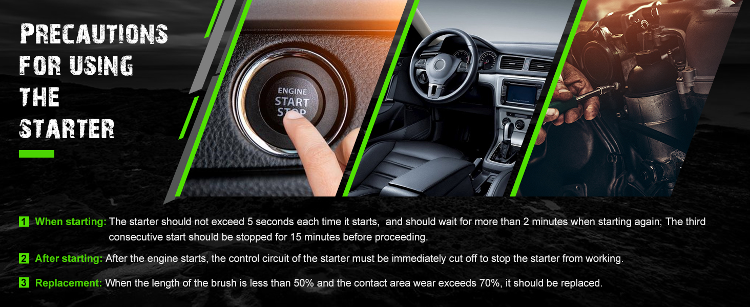
Image 7.1: A dashboard display with various warning lights, illustrating potential indicators of a non-functioning starter or related electrical issues.
- Severe Battery Loss: Ensure the battery is fully charged and in good condition.
- Poor Contact of Starter Circuit and Switch: Check all electrical connections to the starter and ignition switch for corrosion or looseness.
- Short Circuit, Open Circuit, or Grounding in the Excitation Winding or Armature Winding: This indicates an internal electrical fault within the starter or its wiring. Professional diagnosis is required.
- Poor Contact Between Brush and Rectifier: Worn brushes or a dirty commutator can prevent proper electrical contact. Refer to the maintenance section for brush replacement.
- Electromagnetic Switch Coil Short Circuit or Open Circuit: Issues with the solenoid (electromagnetic switch) can prevent the starter from engaging.
- The Control Circuit is Faulty: Problems in the wiring or components that send the signal to the starter.
7.2. Abnormal Starter Operation

Image 7.2: Hands giving a 'thumbs up' gesture over an engine bay, representing confidence in professional quality and problem resolution.
- Abnormal Noise: If the starter makes abnormal noise, it could indicate misalignment, worn gears, or internal damage.
- Starter Idling: If the starter spins but does not engage the engine, the pinion gear or solenoid may be faulty.
- Weak Rotation: A weak rotation can be caused by a low battery, poor electrical connections, or internal starter issues.
- Collision Sound Between Gear and Flying Gear Ring: This often points to improper engagement or a damaged flywheel/pinion.
For complex issues, professional diagnosis and repair are recommended.
8. What's in the Box
Your SCITOO Starter package includes the following:
- 1 x SCITOO Starter Motor (Model 4730920-M030SM)
9. Warranty and Support
For warranty information, technical support, or assistance with your SCITOO Starter, please refer to the documentation provided with your purchase or contact SCITOO customer service directly. Keep your purchase receipt as proof of purchase.