
1. Introduction
This manual provides comprehensive instructions for the installation, operation, and maintenance of the ComMax DR-4UM 4-Button Audio Intercom Lobby Panel. The DR-4UM is designed for use in 4-apartment buildings, facilitating audio communication between visitors at the lobby panel and residents within their apartments.
The DR-4UM functions as a key component of a wired intercom system, requiring integration with compatible ComMax interphone series units, such as the DP-SS (sold separately), and a DC12V power supply (ComMax RF-1A, sold separately).
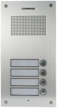
Figure 1: ComMax DR-4UM 4-Button Audio Intercom Lobby Panel (Front View)
2. Package Contents
Please verify that all items listed below are present in your package. If any items are missing or damaged, contact your supplier immediately.
- ComMax DR-4UM 4-Button Lobby Panel x1
- 4-pin Connector x2
- User Manual x1
Note: Additional accessories such as wiring cables, indoor handsets (e.g., DP-SS), power supply (e.g., RF-1A), and electric door strikes are not included and must be purchased separately.
3. Safety Information
Read all instructions carefully before installation and operation. Keep this manual for future reference.
- Ensure the power supply is disconnected before performing any installation or maintenance.
- Only use the specified DC12V, 1Amp power supply (ComMax RF-1A or equivalent).
- Installation should be performed by qualified personnel to prevent electric shock or product damage.
- Do not expose the unit to excessive moisture, rain, or extreme temperatures.
- Avoid placing the unit near strong electromagnetic fields.
4. Setup and Installation
4.1. Compatibility
The DR-4UM lobby panel is designed to be compatible with ComMax interphone series, such as the DP-SS indoor handsets. Ensure all components of your intercom system are compatible before installation.
4.2. Mounting
The DR-4UM is a flush-mounted unit. Select a suitable location at the building entrance, ensuring it is protected from direct weather exposure if possible, and at an appropriate height for visitors.

Figure 2: Installation Dimensions (Measurements in mm)
Refer to Figure 2 for precise dimensions and mounting hole locations. Prepare the wall opening according to these measurements for a flush fit.
4.3. Wiring Diagram
The DR-4UM requires a DC12V, 500mA power source (e.g., ComMax RF-1A). The wiring involves a common 3-wire connection plus individual wires for each apartment.

Figure 3: Wiring Diagram for DR-nUM (DR-4UM) with DP-SS and RF-1A
Follow the wiring diagram in Figure 3 carefully. Connect the lobby panel to the indoor handsets (DP-SS) and the power supply (RF-1A). Ensure all connections are secure and correctly polarized. Incorrect wiring can damage the unit or prevent proper operation.
- Power Connection: Connect the DC12V power supply to the designated terminals (CN3 in the diagram).
- Interphone Connection: Connect the 4-pin connectors from the DR-4UM to the DP-SS indoor units. The diagram shows common wires (1, 2, 3) and individual apartment wires (L1 for each DP-SS).
- Electric Door Strike (Optional): If an electric door strike is used, connect it as shown in the diagram, ensuring it has its own power source.
5. Operating Instructions
The ComMax DR-4UM lobby panel provides simple and direct audio communication.
5.1. Calling an Apartment
- A visitor approaches the lobby panel.
- The visitor identifies the desired apartment number.
- The visitor presses the corresponding call button on the DR-4UM panel.
- An audible signal will sound at the indoor handset (DP-SS) in the selected apartment.
5.2. Two-Way Communication
- Once the resident answers the call from their indoor handset, two-way audio communication is established.
- The visitor can speak into the microphone on the lobby panel.
- The resident can speak into their indoor handset.
- Communication will cease when either party hangs up their handset or after a predetermined time-out period.
6. Maintenance
Regular maintenance ensures the longevity and optimal performance of your ComMax DR-4UM lobby panel.
- Cleaning: Wipe the panel surface with a soft, damp cloth. Do not use abrasive cleaners, solvents, or harsh chemicals, as these can damage the finish.
- Inspection: Periodically check for any loose connections or visible damage to the panel.
- Environmental Protection: While the panel is designed for outdoor use, protecting it from direct, prolonged exposure to extreme weather conditions (heavy rain, direct sunlight, snow) can extend its lifespan.
7. Troubleshooting
If you encounter issues with your DR-4UM lobby panel, refer to the following common problems and solutions.
| Problem | Possible Cause | Solution |
|---|---|---|
| No audio when calling an apartment. |
|
|
| Call button does not respond. |
|
|
| Poor audio quality (static, low volume). |
|
|
If the problem persists after attempting these solutions, please contact ComMax technical support.
8. Specifications
Technical specifications for the ComMax DR-4UM 4-Button Audio Intercom Lobby Panel.

Figure 4: ComMax DR-4UM Technical Specifications
| Feature | Detail |
|---|---|
| Model | DR-4UM |
| Power Source | DC12V, 1Amp (ComMax RF-1A recommended, sold separately) |
| Wiring | Common 3 wires + Individual 1 wire per apartment |
| Communication Type | 2-way audio |
| Mount Type | Flush-mounted |
| Operating Temperature | -10°C ~ 50°C (14°F ~ 122°F) |
| Dimensions (W x H x D) | 142 mm x 250 mm x 50 mm (5.59 x 9.84 x 1.97 inches) |
| Material | Aluminum |
| Color | Silver |
| Item Weight | 907.18 Grams (2 pounds) |
| Compatible Devices | ComMax interphone series (e.g., DP-SS) |
| Connectivity Technology | Wired |
| Control Method | Voice |
| UPC | 730957987658 |
8.1. Communication Distance vs. Cable Diameter
| Cable Diameter (mm) | Max. Distance (m) |
|---|---|
| Ø0.5 | 30 m |
| Ø0.65 | 50 m |
| Ø0.8 | 70 m |
| Ø1 | 100 m |
9. Warranty and Support
For warranty information, please refer to the warranty card included with your product or contact your local ComMax distributor.
For technical support, installation assistance, or troubleshooting beyond the scope of this manual, please contact ComMax customer service or visit the official ComMax website for support resources.


