1. Introduction
The MASTECH MY70 is a reliable and versatile digital multimeter designed for basic electrical measurements. It is suitable for a wide range of applications, including workshop use, hobby projects, and general electrical testing. This manual provides essential information for the safe and effective operation, maintenance, and troubleshooting of your MY70 multimeter.
2. Safety Information
Always observe the following safety precautions to prevent personal injury and damage to the multimeter or equipment under test.
- Read and understand all instructions in this manual before using the multimeter.
- Do not exceed the maximum input values for any function.
- Use caution when working with voltages above 30V AC RMS, 42V peak, or 60V DC. These voltages pose a shock hazard.
- Always disconnect the test leads from the circuit before changing functions or ranges.
- Inspect test leads for damaged insulation or exposed metal before each use. Replace if damaged.
- Ensure the battery cover is securely closed before operation.
- Do not operate the multimeter if it appears damaged or if the case is open.
- Adhere to local and national safety codes.
This device complies with IEC 61010, CE, and RoHS standards.
3. Product Features
The MASTECH MY70 Digital Multimeter offers a range of essential measurement capabilities:
- AC and DC Voltage Measurement
- AC and DC Current Measurement
- Resistance Measurement
- Diode Test
- Continuity Test with Buzzer
- Transistor hFE Test
- Data Hold Function
- Auto Power Off
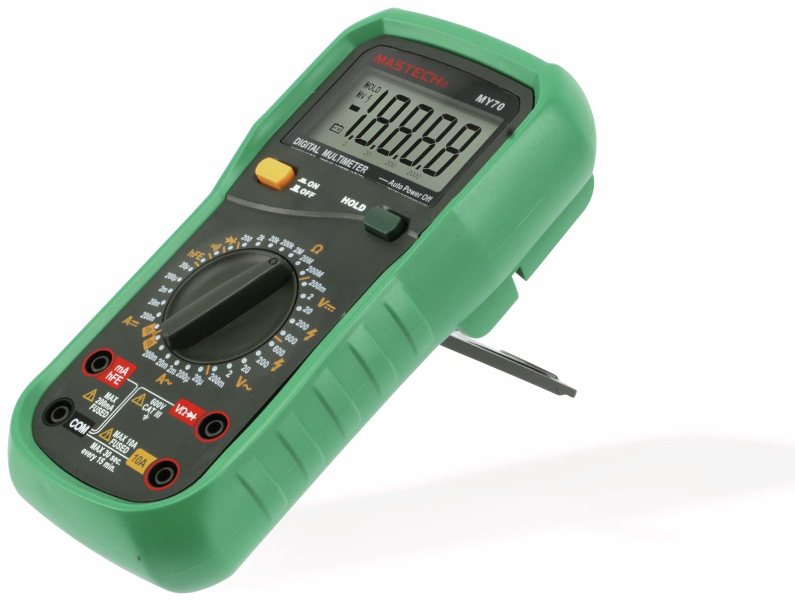
Figure 3.1: Front view of the MASTECH MY70 Digital Multimeter.
4. Package Contents
Verify that all items are present in your package:
- MASTECH MY70 Digital Multimeter
- Test Leads (one red, one black)
- 9V Battery (NEDA 1604 or 6F22 type)
- Transistor Test Socket (hFE adapter)
- User Manual (this document)
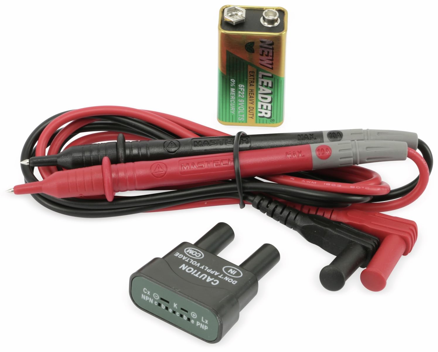
Figure 4.1: MASTECH MY70 Multimeter accessories.
5. Setup
5.1 Battery Installation
- Ensure the multimeter is turned OFF.
- Locate the battery compartment on the back of the unit.
- Unscrew the retaining screw(s) and remove the battery cover.
- Connect the 9V battery to the battery clips, observing correct polarity.
- Place the battery into the compartment and replace the cover, securing it with the screw(s).

Figure 5.1: Rear view with battery compartment.
5.2 Connecting Test Leads
For most measurements, connect the black test lead to the "COM" (common) jack and the red test lead to the "VΩmA" jack. For high current measurements (up to 10A), connect the red lead to the "10A" jack.
6. Operating Instructions
To begin, turn the rotary switch to the desired function and range. Connect the test leads to the circuit or component under test.
6.1 DC Voltage Measurement (V=)
- Set the rotary switch to the desired "V=" range (e.g., 20V, 200V).
- Connect the black test lead to the "COM" jack and the red test lead to the "VΩmA" jack.
- Connect the test leads in parallel across the DC voltage source or component.
- Read the voltage value on the display.
6.2 AC Voltage Measurement (V~)
- Set the rotary switch to the desired "V~" range (e.g., 200V, 600V).
- Connect the black test lead to the "COM" jack and the red test lead to the "VΩmA" jack.
- Connect the test leads in parallel across the AC voltage source or component.
- Read the voltage value on the display.
6.3 DC Current Measurement (A=)
Caution: Always connect the multimeter in series with the circuit when measuring current. Never connect it in parallel across a voltage source.
- Set the rotary switch to the desired "A=" range (e.g., 200µA, 10A).
- For currents up to 200mA, connect the red test lead to the "VΩmA" jack. For currents up to 10A, connect the red test lead to the "10A" jack. The black lead always connects to "COM".
- Open the circuit where current is to be measured and connect the multimeter in series.
- Read the current value on the display.
6.4 Resistance Measurement (Ω)
Caution: Ensure the circuit is de-energized and all capacitors are discharged before measuring resistance.
- Set the rotary switch to the desired "Ω" range (e.g., 200Ω, 2MΩ).
- Connect the black test lead to "COM" and the red test lead to "VΩmA".
- Connect the test leads across the component whose resistance is to be measured.
- Read the resistance value on the display.
6.5 Diode Test (→|)
- Set the rotary switch to the "→|" position.
- Connect the black test lead to "COM" and the red test lead to "VΩmA".
- Connect the red lead to the anode and the black lead to the cathode of the diode. A forward voltage drop (typically 0.5V to 0.8V for silicon diodes) will be displayed.
- Reverse the leads. The display should show "OL" (Overload) for a good diode.
6.6 Continuity Test (•))))
- Set the rotary switch to the "•)))" position.
- Connect the black test lead to "COM" and the red test lead to "VΩmA".
- Connect the test leads across the circuit or component.
- If the resistance is below approximately 50Ω, the buzzer will sound, indicating continuity.
6.7 Transistor hFE Test
- Set the rotary switch to the "hFE" position.
- Insert the transistor (NPN or PNP) into the appropriate sockets on the transistor test adapter.
- Read the hFE (DC current gain) value on the display.
6.8 Data Hold Function
Press the "HOLD" button to freeze the current reading on the display. Press it again to release the hold function and resume live readings.
7. Maintenance
7.1 Cleaning
Wipe the case with a damp cloth and a mild detergent. Do not use abrasives or solvents. Ensure the multimeter is completely dry before use.
7.2 Battery Replacement
When the battery symbol appears on the display, the 9V battery needs to be replaced. Refer to Section 5.1 for battery installation instructions.
7.3 Fuse Replacement
If the current measurement function fails, the fuse may need replacement. The MY70 uses two fuses: a 400mA/250V (F400mA/250V) fuse for the mA range and a 10A/250V (F10A/250V) fuse for the 10A range. To replace a fuse:
- Ensure the multimeter is turned OFF and test leads are disconnected.
- Remove the battery cover and battery.
- Unscrew the additional screws holding the back case.
- Carefully separate the two halves of the case.
- Locate the blown fuse(s) and replace with fuses of the identical type and rating.
- Reassemble the case, ensuring all screws are tightened.
8. Troubleshooting
| Problem | Possible Cause | Solution |
|---|---|---|
| No display or dim display | Low battery or dead battery | Replace the 9V battery. |
| "OL" (Overload) displayed | Input value exceeds selected range or open circuit | Select a higher range or check for an open circuit. |
| Incorrect current reading or no current reading | Blown fuse or incorrect lead connection | Check and replace fuse if necessary. Ensure leads are connected in series and to the correct jacks. |
| Inaccurate resistance reading | Component still energized or parallel components affecting reading | Ensure circuit is de-energized. Isolate the component for accurate measurement. |
9. Specifications
| Parameter | Value |
|---|---|
| Model | MY70 |
| Manufacturer | Mastech |
| Power Source | 9V Battery (NEDA 1604 or 6F22) |
| Dimensions (L x W x H) | 20.5 x 12.5 x 6 cm (approx. 8.07 x 4.92 x 2.36 inches) |
| Weight | Approx. 567 grams (1.25 lbs) |
| Safety Standards | IEC 61010, CE, RoHS |
| Max Operating Temperature | 60°C (140°F) |
| DC Voltage Range | 200mV, 2V, 20V, 200V, 600V |
| AC Voltage Range | 200V, 600V |
| DC Current Range | 200µA, 2mA, 20mA, 200mA, 10A |
| Resistance Range | 200Ω, 2kΩ, 20kΩ, 200kΩ, 2MΩ, 20MΩ |
10. Warranty and Support
For warranty information and technical support, please refer to the official Mastech website or contact your local distributor. Keep your purchase receipt as proof of purchase for warranty claims.
Manufacturer: Mastech
Model Number: MY70


