1. Introduction
This manual provides essential information for the proper installation, operation, and maintenance of the Allen-Bradley Flex I/O 1794-OB16 16-Point D/C Output Module. This module is designed for industrial control applications, providing 16 direct current (DC) output points for various automation tasks. Please read this manual thoroughly before attempting any installation or operation.
2. Product Overview
The Allen-Bradley 1794-OB16 is a Flex I/O digital DC output module. It features 16 output points and is designed to interface with a Flex I/O terminal base, such as the TB3, for secure wiring connections. The module operates on a 24 Volts DC source.

Figure 2.1: Front view of the 1794-OB16 module showing the 16 output points and screw terminals for wiring connections. The module is clearly labeled 'Allen-Bradley Flex I/O 1794-OB16' and '24 VDC SOURCE OUTPUT'.
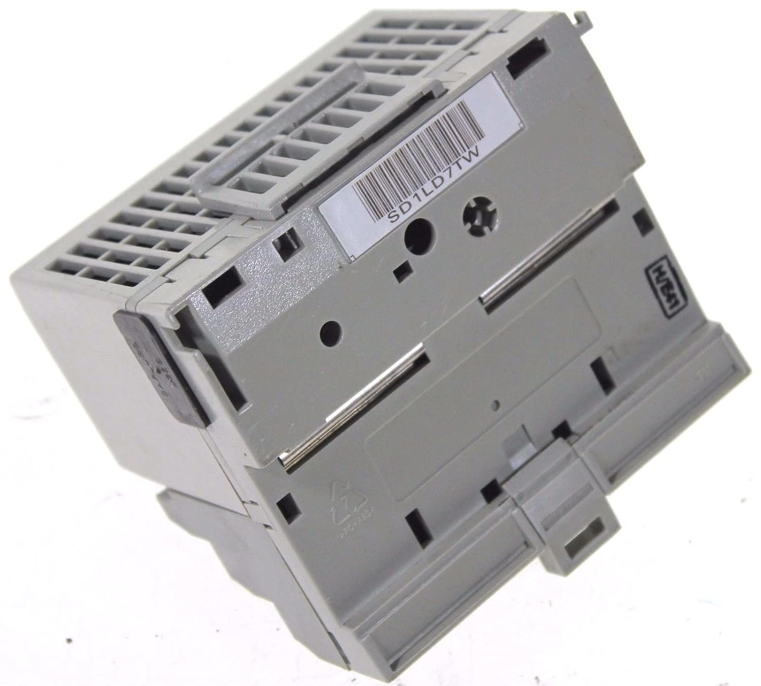
Figure 2.2: Side view of the 1794-OB16 module, illustrating the mounting mechanism and the compact design. A barcode label 'SD1LD7TW' is visible on the side.

Figure 2.3: Detailed view of the product label on the 1794-OB16 module, indicating part number 96221871, Flexbus current, output rating (10-31.2VDC, 500mA), and compliance markings (UL, SP, CE).
3. Setup and Installation
The 1794-OB16 module is designed for screw mount installation and utilizes screw-type connectors for wiring. Proper installation is crucial for reliable operation.
3.1 Mounting the Module
- Ensure the power to the Flex I/O system is disconnected before installation.
- Align the 1794-OB16 module with the desired slot on the Flex I/O terminal base (e.g., 1794-TB3).
- Gently press the module onto the terminal base until it clicks into place, ensuring a secure mechanical and electrical connection.
- Verify that the module is firmly seated and does not wobble.
3.2 Wiring Connections
The module provides 16 output points. Use appropriate gauge wiring for 24V DC applications.
- Refer to your system's wiring diagrams for specific connections to external devices.
- Strip wire insulation to the recommended length for the screw terminals.
- Insert each wire into its corresponding screw terminal on the terminal base.
- Tighten the screw terminals securely to ensure good electrical contact. Do not overtighten.
- Double-check all wiring for correct polarity and connection to the intended output devices.
4. Operating Instructions
Once installed and wired, the 1794-OB16 module functions as a digital output interface for your control system.
4.1 Power-Up
- After verifying all connections, apply 24 Volts DC power to the Flex I/O system.
- Observe the status indicators on the module (if present) to confirm proper power and communication.
4.2 Output Control
The 16 output points are controlled by the programmable logic controller (PLC) or other control device connected to the Flex I/O system. Each output can be individually switched ON or OFF based on the logic programmed in the controller.
- Ensure your control program is correctly configured to address the 1794-OB16 module's output points.
- Monitor the status of connected output devices to confirm correct operation.
5. Maintenance
The Allen-Bradley 1794-OB16 module is designed for robust industrial environments. Regular, simple maintenance can help ensure long-term reliability.
- Visual Inspection: Periodically inspect the module and its wiring for any signs of damage, loose connections, or corrosion.
- Cleaning: If necessary, gently clean the exterior of the module with a soft, dry, lint-free cloth. Do not use abrasive cleaners or solvents. Ensure power is disconnected before cleaning.
- Environmental Control: Ensure the operating environment remains within the specified temperature and humidity ranges to prevent premature component failure.
6. Troubleshooting
If the 1794-OB16 module is not functioning as expected, consider the following troubleshooting steps:
- No Output:
- Verify that the 24V DC power supply to the Flex I/O system is active and stable.
- Check all wiring connections to the output devices for continuity and proper termination.
- Confirm that the PLC or control program is commanding the specific output point to be ON.
- Inspect the module's status indicators for any error codes or abnormal behavior.
- Incorrect Output Voltage/Current:
- Ensure the load connected to the output is within the module's specified current rating (500mA per output).
- Check for short circuits or overloads on the output line.
- Module Not Communicating:
- Verify the module is correctly seated on the terminal base.
- Check the Flex I/O adapter module for communication errors.
If issues persist after performing these checks, consult the Allen-Bradley Flex I/O system documentation or contact technical support.
7. Specifications
| Specification | Value |
|---|---|
| Brand | Allen-Bradley |
| Model Number | 1794-OB16 |
| Item Weight | 3 Pounds |
| Manufacturer | allen bradley |
| Connector Type | Screw |
| Number Of Contacts | 16 |
| Mounting Type | Screw Mount |
| Material | Plastic |
| Color | Grey |
| Voltage | 24 Volts DC |
| Number Of Poles | 16 |
| Output Current Rating | 500mA per output (as per image label) |
8. Warranty and Support
For information regarding product warranty, technical support, and service, please refer to the official documentation provided by Allen-Bradley or visit their official website. Specific warranty terms and support procedures may vary based on region and purchase agreement.


