
1. Introduction
This manual provides detailed instructions for the installation, operation, and maintenance of your Dakota Digital VHX-88C-PU-K-R Analog Dash Gauges. This system is designed as a direct-fit instrument cluster replacement for 1988-1994 Chevrolet and GMC Pickup Trucks, including 1992-1994 SUVs. It integrates modern instrumentation with a classic aesthetic, offering precise monitoring of your vehicle's vital functions.
The VHX Series features fully lit needles, backlit faces, and highly visible LCD message centers, powered by micro-controlled precision stepper motors and solid-state sensors for accuracy.
2. Safety Information
Always disconnect the vehicle's battery before beginning any electrical work to prevent electrical shock or damage to the vehicle's electrical system. Ensure all wiring connections are secure and properly insulated. Consult a professional automotive technician if you are unsure about any installation steps. This product is intended for automotive use only. Do not modify the unit or its components, as this may void the warranty and create safety hazards.
3. Package Contents
Verify that all components listed below are present in your VHX-88C-PU-K-R kit before beginning installation. If any items are missing or damaged, contact Dakota Digital customer support.

Figure 3.1: Contents of the VHX-88C-PU-K-R kit. This image displays the main VHX display unit, a universal sender pack with various sensors and bushings, a control box, a switch harness, a CAT5 cable, and the installation manual.
- VHX Display Unit
- Universal Sender Pack (Oil Pressure, Water Temperature, Speedometer Pulse Generator)
- Control Box
- Switch Harness
- CAT5 Cable
- Installation Manual
- Cut Template and Cut Guard (for bezel modification, if required)
4. Setup and Installation
This section outlines the steps for installing your Dakota Digital VHX instrument system. Refer to the detailed installation manual included in your kit for specific wiring diagrams and vehicle-specific instructions.
4.1 Pre-Installation Checks
- Ensure the vehicle's battery is disconnected.
- Gather all necessary tools (screwdrivers, wire strippers, crimpers, multimeter, etc.).
- Review the complete installation manual before starting.
4.2 Removing the Factory Instrument Cluster
Carefully remove the dashboard bezel and the existing instrument cluster from your vehicle. Disconnect all electrical connectors and the speedometer cable (if mechanical).
4.3 Sensor Installation
Install the provided sending units for oil pressure, water temperature, and the speedometer pulse generator. The water temperature sender includes bushings for various NPT sizes (1/4", 3/8", 1/2") as well as 12mm and 16mm for GM & LS applications. The oil pressure sender is 1/8" NPT. Ensure proper sealing and thread engagement for all sensors.
4.4 Wiring Connections
Connect the VHX display unit to the control box using the provided CAT5 cable. Wire the control box to the vehicle's power, ground, illumination, and accessory circuits as per the detailed wiring diagram. Connect the sender pack wires to the corresponding inputs on the control box. Ensure all indicator wires (turn signals, high beam, check engine, parking brake, cruise control) are correctly connected.
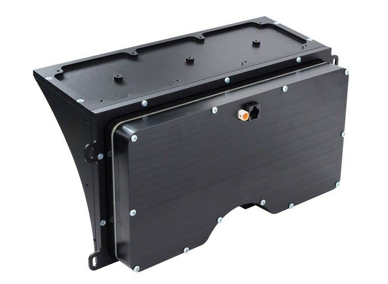
Figure 4.1: Rear view of the VHX display unit, illustrating the connection points for the CAT5 cable and other wiring harnesses that connect to the control box and vehicle's electrical system.
4.5 Mounting the VHX Display
The VHX system replaces the entire factory instrument cluster and lens assembly. Mount the new billet aluminum housing with optical grade polycarbonate lenses into the dashboard opening. Secure it using the factory mounting points or provided hardware. Reinstall the dashboard bezel.
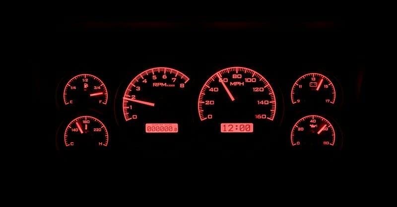
Figure 4.2: Front view of the Dakota Digital VHX instrument cluster, showing the gauges and digital displays. This image represents the unit as it would appear when installed in the vehicle's dashboard.
4.6 Initial Power-Up and Calibration
Reconnect the vehicle's battery. Turn the ignition to the accessory or run position. The VHX system will perform an initial self-test. Follow the on-screen prompts or refer to the detailed manual for speedometer calibration and initial setup of the clock and odometer.
5. Operating Instructions
The VHX system provides both analog gauge readings and digital message center displays. The system is user-customizable for various display feedback options.

Figure 5.1: The Dakota Digital VHX dash gauges illuminated with red backlighting, showing the speedometer, tachometer, and auxiliary gauges in operation, along with the digital message centers.
5.1 Analog Gauges
- Speedometer: Displays vehicle speed from 0-160 MPH.
- Tachometer: Displays engine RPM from 0-8000 RPM.
- Oil Pressure: Displays engine oil pressure from 0-80 psi.
- Water Temperature: Displays engine coolant temperature from 100-260°F.
- Fuel Level: Displays fuel tank level (E, 1/4, 1/2, 3/4, F).
- Voltmeter: Displays vehicle system voltage from 9-17 VDC.
5.2 Digital Message Centers
The LCD message centers provide additional vehicle information and performance metrics.
- Standard Displays:
- Odometer (One-time user settable, Million Mile)
- Dual (A/B) Trip Meter (0-9,999.9)
- Clock (12 hour)
- Performance Meters:
- 0-60 MPH Timer (0-100 kmh)
- 1/4 mile time
- 1/4 mile end speed (trap speed)
- High speed recall
- High RPM recall
5.3 Built-In Indicators
The VHX system includes integrated indicators for various vehicle functions:
- Turn Signals (Left/Right)
- High Beam
- Check Engine
- Parking Brake
- Cruise Control (On/On & Engaged when vehicle is equipped)
- Gear Position (Optional GSS-3000 sensor required, sold separately)
6. Maintenance
The Dakota Digital VHX system is designed for long-term reliability with minimal maintenance.
6.1 Cleaning
Clean the optical grade polycarbonate lenses and the billet aluminum housing with a soft, damp cloth. Avoid abrasive cleaners or solvents, as these can damage the finish and lens material.
6.2 Software Updates
Periodically check the Dakota Digital website for any available firmware updates for your VHX system. Updates may offer new features or performance enhancements. Follow the instructions provided with the update carefully.
7. Troubleshooting
If you encounter issues with your VHX system, refer to the following common troubleshooting steps. For more complex problems, consult the full installation manual or contact Dakota Digital technical support.
| Problem | Possible Cause | Solution |
|---|---|---|
| No power to display | Blown fuse, loose power connection, incorrect wiring. | Check vehicle fuses, verify power and ground connections, ensure wiring matches diagram. |
| Inaccurate speedometer reading | Incorrect calibration, faulty speed sensor, wiring issue. | Recalibrate speedometer according to manual, check speed sensor connection and function. |
| Gauge not reading (e.g., oil pressure) | Faulty sender, loose sender wire, incorrect sender type. | Verify sender unit is correctly installed and wired, check for continuity in sender wire. |
| Digital display blank or flickering | Loose CAT5 cable connection, power fluctuation. | Ensure CAT5 cable is securely connected between display and control box. Check vehicle voltage stability. |
8. Specifications
- Model: VHX-88C-PU-K-R
- Compatibility: 1988-1994 Chevrolet/GMC Pickup Trucks, 1992-1994 SUVs
- Material: Billet Aluminum Housing, Optical Grade Polycarbonate Lenses
- Voltage: 12 VDC
- Speedometer Range: 0-160 MPH
- Tachometer Range: 0-8000 RPM
- Oil Pressure Range: 0-80 psi
- Water Temperature Range: 100-260°F
- Voltmeter Range: 9-17 VDC
- Dimensions (Product): Approximately 24 x 14 x 8 inches (L x W x H)
- Manufacturer: Dakota Digital
9. Warranty and Support
Dakota Digital instrumentation systems are supported by an unrivaled limited lifetime warranty. For warranty claims, technical assistance, or further support, please contact Dakota Digital directly. Refer to the official Dakota Digital website or the included installation manual for the most current contact information and warranty details.