
1. Introduction and Safety Guidelines
This digital multimeter is designed and manufactured in accordance with IEC-61010 safety requirements for electronic measuring meters and hand-held digital multimeters. It complies with the requirements for 600V CAT IV, 1000V CAT III, and pollution degree 2 as specified in IEC61010. Before using this meter, please read this manual carefully and observe all relevant safety guidelines.
The BSIDE ADM08A is a hand-held digital multimeter with True RMS measurement capabilities. It features a large LCD screen with backlight for easy reading and provides overload protection and low battery indications. This multi-functional meter is suitable for professionals, educational institutions, enthusiasts, and home use.
Important Safety Information:
- Always ensure the meter is set to the correct function and range before making measurements.
- Do not exceed the maximum input values for any range.
- Exercise extreme caution when working with live circuits.
- Inspect test leads for damage before each use. Replace if insulation is compromised.
- Do not operate the meter if it appears damaged or if the battery cover is not properly closed.
- Refer to the 'Protective tube-based protection' section in specifications for fuse details.
2. Product Overview

Figure 2.1: Front view of the BSIDE ADM08A Digital Multimeter with red and black test leads connected. The large LCD screen displays 'OL' (Overload) and the rotary dial is set to a measurement function. The input jacks for probes are visible at the bottom.

Figure 2.2: Back view of the BSIDE ADM08A Digital Multimeter, showing the battery compartment cover and a warning label regarding electrical shock and fuse replacement. The integrated kickstand is folded in.

Figure 2.3: Side view of the BSIDE ADM08A Digital Multimeter with its integrated kickstand extended, allowing the device to stand upright for easier viewing during use.
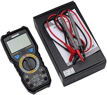
Figure 2.4: The BSIDE ADM08A Digital Multimeter displayed alongside its retail packaging and the included red and black test leads, indicating the complete product contents.
3. Setup and Initial Use
3.1 Battery Installation
The BSIDE ADM08A multimeter requires 4 x 1.5V AA batteries for operation. To install or replace batteries:
- Ensure the multimeter is turned off and disconnect all test leads from the input terminals.
- Locate the battery compartment on the back of the unit (refer to Figure 2.2).
- Use a screwdriver to open the battery compartment cover.
- Insert four 1.5V AA batteries, observing the correct polarity (+/-) as indicated inside the compartment.
- Replace the battery compartment cover and secure it with the screw.
A Low Battery indication will appear on the LCD screen when the battery voltage drops below the normal operating level, signaling that batteries need replacement.
3.2 Connecting Test Leads
Connect the red test lead to the 'VΩmA' or '20A' input jack, and the black test lead to the 'COM' (common) input jack. Ensure connections are firm before use.
4. Operating Instructions
The multimeter's rotary dial is used to select the desired measurement function. The LCD display will show the measured value, unit symbols, and other indicators such as 'OL' for over-range or a battery icon for low battery.
4.1 DC Voltage Measurement
- Turn the rotary dial to the 'V=' (DC Voltage) position.
- Connect the red test lead to the positive (+) side of the circuit and the black test lead to the negative (-) side.
- Read the voltage value on the LCD. The meter supports ranges: 600mV, 6V, 60V, 600V, 1000V.
4.2 AC Voltage Measurement
- Turn the rotary dial to the 'V~' (AC Voltage) position.
- Connect the test leads across the AC voltage source.
- Read the voltage value on the LCD. The meter supports ranges: 6V, 60V, 600V, 1000V.
4.3 DC Current Measurement
- Turn the rotary dial to the 'A=' (DC Current) position.
- For currents up to 600mA, connect the red test lead to the 'VΩmA' jack. For currents up to 20A, connect the red test lead to the '20A' jack. The black lead remains in 'COM'.
- Connect the meter in series with the circuit to be measured.
- Read the current value on the LCD. The meter supports ranges: 60µA, 6mA, 60mA, 600mA, 20A.
4.4 AC Current Measurement
- Turn the rotary dial to the 'A~' (AC Current) position.
- Follow the same test lead connection procedure as for DC Current measurement.
- Connect the meter in series with the circuit.
- Read the current value on the LCD. The meter supports ranges: 6mA, 60mA, 600mA, 20A.
4.5 Resistance Measurement
- Turn the rotary dial to the 'Ω' (Resistance) position.
- Ensure the circuit or component is de-energized before measuring resistance.
- Connect the test leads across the component.
- Read the resistance value on the LCD. The meter supports ranges: 600Ω, 6kΩ, 60kΩ, 600kΩ, 6MΩ, 60MΩ.
4.6 Capacitance Measurement
- Turn the rotary dial to the 'F' (Capacitance) position.
- Ensure the capacitor is fully discharged before measurement to prevent damage to the meter.
- Connect the test leads across the capacitor terminals.
- Read the capacitance value on the LCD. The meter supports ranges: 6nF, 60nF, 600nF, 6µF, 60µF, 600µF, 6mF.
5. Maintenance
5.1 Battery Replacement
When the low battery indicator appears on the display, replace the 4 x 1.5V AA batteries as described in Section 3.1. Always use fresh batteries of the specified type.
5.2 Cleaning
To clean the meter, wipe the case with a damp cloth and a mild detergent. Do not use abrasives or solvents. Ensure the meter is completely dry before use.
5.3 Storage
When storing the meter for extended periods (e.g., when relative humidity is less than 70%), remove the batteries to prevent leakage and damage. Store in a temperature range of -10°C to 60°C.
5.4 Fuse Replacement
If the current measurement function fails, the internal fuse may need replacement. Refer to the specifications for the correct fuse type and rating. Fuse replacement should only be performed by qualified personnel.
6. Troubleshooting
- Display shows 'OL': This indicates an over-range condition. The measured value exceeds the selected range. Switch to a higher range or verify the circuit.
- No display or faint display: Check battery installation and charge. Replace batteries if necessary.
- Incorrect readings: Ensure test leads are properly connected and not damaged. Verify the correct function and range are selected. Ensure the circuit is de-energized for resistance/capacitance measurements.
- Current measurement not working: Check the fuse. Ensure the test lead is connected to the correct current input jack (mA or 20A).
7. Specifications
| Parameter | Specification |
|---|---|
| Operating Environment | 600V CAT IV and 1000V CAT III, Pollution Degree 2, Altitude < 2000 m |
| Ambient Temperature | 0~40°C (RH < 80% and T < 10°C) |
| Storage Temperature | -10~60°C (RH < 70%, remove battery) |
| Temperature Coefficient | 0.1 x Accuracy/°C (<18°C or >28°C) |
| Max Voltage (Terminal to Ground) | 1000V DC or 750V AC RMS |
| Protective Tube (mA position) | FF 630mA/250V |
| Protective Tube (A position) | FF 20A/250V |
| Conversion Rate | Approximately 3 times per second |
| Monitor | 6000 counts LCD display |
| Over-range Indication | "OL" on LCD screen |
| Low Battery Indication | Battery icon appears |
| Input Polarity Indication | '-' automatically appears |
| Power Supply | 4 x 1.5V AA battery |
| Dimensions (L x W x H) | 184.5 mm x 88 mm x 39 mm |
| Weight | Approximately 420g (including battery) |
| Precision Accuracy | ±(%readings + digits) |
| DC Voltage Ranges | 600mV/6V/60V/600V/1000V (±0.5%+3) |
| AC Voltage Ranges | 6V/60V/600V/1000V (±0.8%+3) |
| DC Current Ranges | 60µA/6mA/60mA/600mA (±0.8%+3), 20A (±1.2%+3) |
| AC Current Ranges | 6mA/60mA/600mA (±1.0%+3), 20A (±1.5%+3) |
| Resistance Ranges | 600Ω/6kΩ/60kΩ/600kΩ/6MΩ (±0.8%+3), 60MΩ (±1.2%+3) |
| Capacitance Ranges | 6nF/60nF/600nF/6µF/60µF/600µF/6mF (±4.0%+3) |
8. Warranty and Support
The warranty period for this product is one year from the ex-factory date. This warranty covers manufacturing defects under normal use conditions.
For technical support or warranty claims, please contact your retailer or the manufacturer's customer service. Keep your purchase receipt as proof of purchase.


