
1. Introduction
This manual provides essential information for the safe and efficient operation of your COTEK SP-2000-112 Pure Sine Wave Inverter. This new generation inverter offers high efficiency, high power density, and selectable output voltage and frequency, housed in a robust aluminum case. Please read this manual thoroughly before installation and use.
The SP-2000-112 is designed to convert 12VDC power to 120VAC 2000W pure sine wave output, suitable for a wide range of sensitive electronic equipment.
2. Safety Information
Important Safety Instructions:
- Read all instructions before operating the inverter.
- Do not expose the inverter to rain, moisture, or excessive heat.
- Ensure proper ventilation around the inverter to prevent overheating.
- Connect the inverter only to a 12VDC power source.
- Always disconnect the DC power before performing any maintenance or wiring.
- This inverter is designed for indoor use (Type 1 Indoor Aluminum Enclosure).
- California Proposition 65 Warning: Product may contain materials cautioned by California Proposition 65.
3. Product Features
The COTEK SP-2000-112 Inverter includes the following key features:
- Pure sine wave output for sensitive electronics.
- Power ON / OFF remote control capability (Green Terminal).
- Input & output fully isolation for enhanced safety.
- Temperature & load controlled cooling fan for optimal performance.
- User-friendly interface for easy operation.
- Output frequency 50/60 Hz selectable by DIP switch.
- Output voltage DIP switch selectable.
- Power saving mode adjustable via variable resistor.
- 3-color LED status indicators for quick status checks.
- Input protection: Reverse Polarity (Fuse) / Under Voltage / Over Voltage.
- Output protection: Short Circuit / Overload / Over Temperature.
- Type 1 Indoor Aluminum Enclosure.
- E13 / UL / CE / FCC approved.
4. Product Overview
Familiarize yourself with the components and connections of your SP-2000-112 inverter.

Figure 4.1: Overall view of the COTEK SP-2000-112 Pure Sine Wave Inverter. This image displays the blue and grey casing with the "COTEK Pure sine wave Inverter SP-2000" branding visible on the top surface.

Figure 4.2: Rear view of the inverter, highlighting the dual GFCI 120VAC outlets, the power ON/OFF switch, and the DIP switches for frequency and voltage selection. Ventilation grilles are also visible.

Figure 4.3: Detailed close-up of the inverter's rear panel. This view clearly shows the two GFCI protected AC output receptacles, the main power switch, the DIP switches (labeled S1), and the remote control terminal (TRC) port.
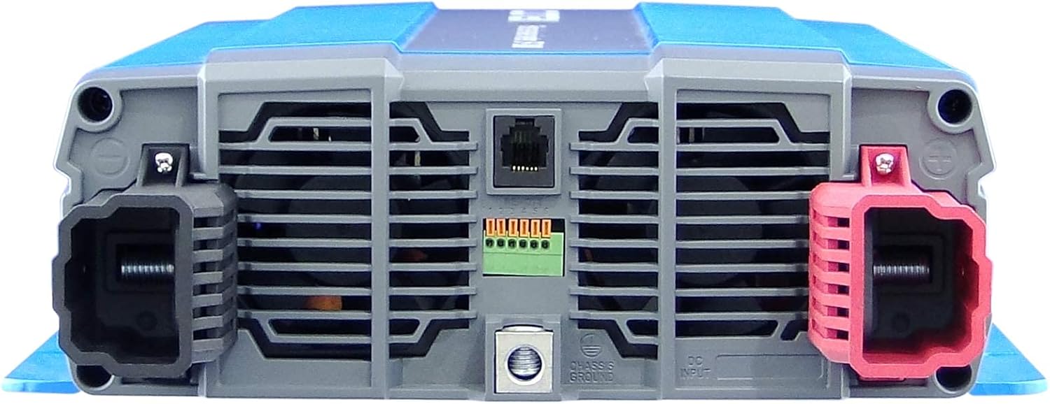
Figure 4.4: Front view of the inverter, displaying the large DC input terminals (red for positive, black for negative) and the chassis ground connection point. Ventilation grilles are present on this side as well.

Figure 4.5: Side profile of the COTEK SP-2000-112 inverter, showcasing its compact and robust aluminum casing design.
5. Setup and Installation
Proper installation is crucial for the safe and efficient operation of your inverter. Follow these guidelines:
- Mounting: Choose a dry, well-ventilated location away from direct sunlight, heat sources, and flammable materials. Ensure adequate clearance around the inverter for airflow, especially around the cooling fan vents.
- DC Input Connection: Connect the inverter directly to a 12VDC battery bank using appropriately sized cables. Ensure correct polarity: connect the positive (+) terminal of the inverter to the positive terminal of the battery, and the negative (-) terminal of the inverter to the negative terminal of the battery. Use the provided DC input terminals.
- Grounding: Connect the chassis ground terminal of the inverter to a reliable earth ground or vehicle chassis ground.
- AC Output Connection: Plug your AC appliances into the GFCI protected AC outlets on the rear panel of the inverter. Ensure the total wattage of connected appliances does not exceed the inverter's rated output (2000W).
- Remote Control (Optional): If using a remote control (e.g., CR-8 or CR-16A, sold separately), connect it to the TRC port on the rear panel.
Note: Always ensure all connections are secure and properly insulated before applying power.
6. Operating Instructions
Once installed, operating the SP-2000-112 inverter is straightforward:
- Power On: Flip the main power switch on the rear panel to the "ON" (I) position. If using a remote control, activate it to power on the inverter.
- Status Indicators: Observe the 3-color LED status indicators. These LEDs provide information on the inverter's operational status, including power, fault conditions, and warnings. Refer to the specifications section for detailed LED indications.
- Output Frequency/Voltage Selection: The inverter's output frequency (50/60 Hz) and voltage are selectable via DIP switches (S1) on the rear panel. Adjust these settings according to the requirements of your connected appliances. Refer to the product specifications for DIP switch configurations.
- Power Saving Mode: The inverter features a power saving mode, adjustable via a variable resistor. This mode reduces power consumption when no load or a very light load is detected. Adjust as needed to optimize battery life.
- Power Off: To turn off the inverter, flip the main power switch to the "OFF" (O) position or use the remote control.
7. Maintenance
Regular maintenance ensures the longevity and reliable performance of your inverter:
- Cleaning: Keep the inverter clean and free from dust and debris. Use a dry, soft cloth for cleaning. Do not use liquid cleaners.
- Ventilation: Periodically check that the cooling fan vents are clear and unobstructed. The temperature and load controlled cooling fan will activate as needed to maintain optimal operating temperature.
- Connections: Periodically inspect all electrical connections (DC input, AC output, ground) to ensure they are tight and free from corrosion.
- Storage: If storing the inverter for an extended period, ensure it is in a cool, dry place. Disconnect it from all power sources.
8. Troubleshooting
The SP-2000-112 inverter is equipped with various protection features. If the inverter stops functioning or indicates a fault, refer to the following common issues and their solutions:
| Problem | Possible Cause | Solution |
|---|---|---|
| No AC Output / Inverter Off |
|
|
| GFCI Outlet Tripped | Ground fault detected on AC output. | Disconnect all AC loads, press the "RESET" button on the GFCI outlet. Reconnect loads one by one to identify the faulty appliance or wiring. |
| Inverter Fan Not Running | Inverter is not under sufficient load or temperature to activate fan. | This is normal operation. The fan is temperature and load controlled. If the inverter is hot and under load, and the fan is still not running, contact support. |
If the problem persists after attempting these solutions, contact qualified service personnel or COTEK customer support.
9. Specifications
Detailed technical specifications for the COTEK SP-2000-112 Pure Sine Wave Inverter:
| Specification | Value |
|---|---|
| Product Dimensions | 18 x 15 x 11 inches |
| Item Weight | 1 pounds |
| ASIN | B01L0PW4IY |
| Item model number | SP-2000 Series |
| Batteries Required | 1 Unknown batteries required. |
| Manufacturer | Cotek |
| Brand | COTEK |
| Recommended Uses For Product | Vehicle |
| Power Source | Battery Powered |
| Wattage | 2000 watts |
| Model Name | SP Series |
| AC Regulation | ±3% |
| Rated Power | 2000VA |
| Surge Power (1 Sec.) | >3500VA |
| Maximum Output Power (1 Min) | 2300VA~2400VA (100%~115%) |
| Output Waveform | Pure Sine Wave (THD<5%@Normal Load) |
| Frequency | 50/60 Hz ±0.5% |
| DC Voltage | 12VDC |
| No Load Current | 10.5-16.5VDC |
| Efficiency (Max.) | 92% |
| Input Under Voltage Protection | 10.0 ±0.3VDC |
| Input Under Voltage Alarm | 11.0 ±0.3VDC |
| Input Under Voltage Recovery | 12.5 ±0.3VDC |
| Input Over Voltage Protection | 16.5 ±0.3VDC |
| Input Over Voltage Recovery | 14.5 ±0.3VDC |
| Output Overload | Shutdown output, restart to recover |
| Output Short | Shutdown output, restart to recover |
| Over Temperature | Heat sink temperature over 80°C ±5°C, shutdown output voltage, recover automatically after heat sink temperature goes down to 60°C ±5°C |
| DC Input Reverse Polarity | By fuse |
| Operating Temp. | -20°C ~ +40°C |
| Storage Temp. | -30°C ~ +70°C |
| Storage Temp. & Humidity | 10 ~ 95% RH |
| Safety Standards | Certified UL 458, E13 |
| EMC Standards | Certified FCC class A, EN 55022, EN 55024, EN 61000-3-2, EN 61000-3-3, EN 61000-4-2, 3, 4, 5, 6, 8, 11 |
| E-mark | Certified CISPR 25, ISO 11452-2, ISO 7637-2 |
| Remote Control (Optional) | CR-8 / CR-16 |
| LED Indicator | Input voltage level, output load level and faulty status |
| Dry Contact Terminal | By relay |
| Remote Control Terminal | 6-pin green terminal |
| Dimension (W x H x D) | 443x232x103mm / 17.6x9.1x4.06 inch |
| Packing | 5.24kg / 4pcs / 21.6kg / 3.58CUFT |
| Cooling | Temperature & load controlled cooling fan |
| Application | Commercial appliances, portable power equipment, vehicle, yacht and off-grid Solar power systems, etc. |
Note: Some specifications are derived from the technical diagram image (Figure 4.6) and product description.

Figure 4.6: Diagram illustrating the detailed technical specifications and features of the COTEK SP-2000 series inverters, including various models and their respective electrical characteristics, protections, and certifications.
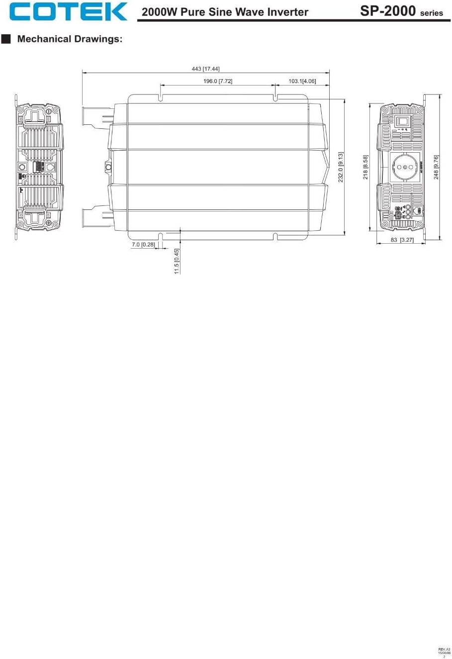
Figure 4.7: Mechanical drawings providing precise dimensions (in mm and inches) of the COTEK SP-2000 series inverter from multiple perspectives (top, front, side), useful for installation planning.
10. Warranty and Support
COTEK products are manufactured to high quality standards. For warranty information or technical support, please contact your authorized COTEK dealer or visit the official COTEK website. Keep your purchase receipt as proof of purchase for any warranty claims.
Optional protection plans may be available for extended coverage. Refer to your point of purchase for details on available protection plans.


