1. Introduction
Thank you for choosing the MiLocks BTF-02AQ Electronic Keyless Entry Door Lock. This manual provides detailed instructions for the installation, programming, operation, and maintenance of your new keypad door lock. This keyless entry deadbolt and handle combo is designed for easy installation on both left-handed and right-handed doors, accommodating thicknesses between 1 1/4" and 1 7/8".
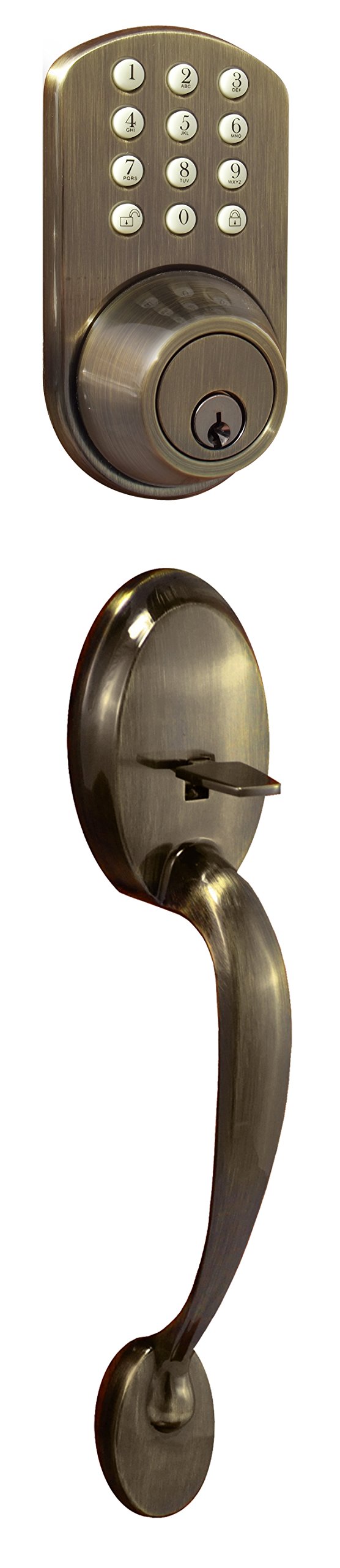
Figure 1: MiLocks BTF-02AQ Electronic Keyless Entry Door Lock with Passage Handle Set Combo.
2. Product Features
- Keyless Keypad Entry: Allows for up to 6 programmable user codes.
- Glow-in-the-Dark Keypad: Enhances visibility and operation in low-light conditions.
- Adjustable Design: Compatible with both left-handed and right-handed doors.
- Easy Programming: Simple keypad procedure for adding or deleting user codes.
- Adjustable Latch: Features two backset settings (2 3/8" and 2 3/4") for versatile installation.
- Audible Tones: Provides feedback for locking, unlocking, and low battery warnings.
3. Installation Guide
A Philips screwdriver is the only tool required for installation. Ensure your door thickness is between 1 1/4" and 1 7/8".
3.1. Installing the Strike Plate
- Position the strike plate on the door frame, aligning it with the latch bore hole.
- Use the included screws to fasten the strike plate securely onto the door frame.
3.2. Installing the Door Latch
The door latch has two settings for the backset (distance from the door edge to the center of the bore hole): 2 3/8" and 2 3/4".
- If your bore hole is 2 3/4" from the edge of the door: Twist the latch to extend it, then twist it back to fit.
- If your bore hole is 2 3/8" from the edge of the door: Twist the latch to retract it, then twist it back to fit.
- Before inserting the latch, ensure the 'UP' label on the latch is oriented correctly.
- Insert the latch into the door and secure it with the included screws.
- Test the latch mechanism by using a screwdriver to simulate the drive bar. Keep the latch in the UNLOCKED position for the next step.
3.3. Installing the Front Module
- Remove the keys from the front module to avoid complications during installation.
- Locate the wire connection and the drive bar on the back of the front module. The drive bar is used to engage the latch by turning.
- Carefully feed the connection wire through the bottom opening of the mounting plate and the drive bar through the center slot.
- It is crucial that the drive bar is oriented vertically when going through the cross slot of the latch. Incorrect orientation will prevent the lock from functioning properly.
- Fasten the mounting plate with screws, but do not tighten them completely yet to allow for slight adjustments.
3.4. Installing the Back Module
- Remove the battery cover from the back module. Note the mounting holes.
- Ensure the thumb-turn on the back module is in the UNLOCKED position, matching the latch. To do this, turn the thumb-turn AWAY from the latch.
- Locate the connection wire and the cross slot for the drive bar on the back module.
- Connect the two wires from the front and back modules. This connection will later provide power to the keypad.
- Install the back module, ensuring the drive bar goes into the cross slot.
- Secure the back module with the mounting screws. Once both modules are in place, tighten all screws securely.
- Insert 4 brand new AA Alkaline batteries into the battery tray.
- Slide the battery cover back on.
- Test the lock by engaging it using the thumb-turn on the back module and then with the key on the front module.
3.5. Installation Tutorial Video
Video 1: MiLocks Keyless Entry Deadbolt Door Installation Tutorial. This video guides you through the complete installation process of the MiLocks keypad deadbolt.
4. Operating Instructions
This section details how to program and use your MiLocks keypad door lock.
4.1. Keypad Controls
Inside the battery compartment, you will find the main controls:
- C Button: Clear button, used for clearing codes.
- S Button: Set button, used for programming codes.
- 1&2 Switch: This switch serves two purposes:
- Changes the rotation of the drive bar (depending on whether the deadbolt was installed on a left or right side).
- Must be set to the '2' position to program user codes.
4.2. Programming User Codes
To add and store a user code:
- Ensure the 1&2 switch is set to the '2' position. You will hear a beep.
- Press and release the 'S' button (you will hear a beep).
- On the exterior keypad, enter your preferred code (2-8 digits), followed by the Unlock button. A double beep confirms the code is saved. A triple beep indicates an error; please try again.
- Repeat these steps to add more user codes.
4.3. Clearing User Codes
To clear all stored user codes:
- Ensure the 1&2 switch is set to the '2' position.
- Press and hold the 'C' button for 10-15 seconds until you hear a double beep. This confirms all saved codes are cleared. A triple beep indicates an error; please try again.
To remove a specific stored user code:
- Ensure the 1&2 switch is set to the '2' position.
- Press and release the 'C' button (you will hear a beep).
- On the exterior keypad, enter the previously stored code you wish to remove, followed by the Unlock button. A double beep confirms the code is removed. A triple beep indicates an error; please try again.
4.4. Programming Tutorial Video
Video 2: MiLocks Keyless Entry Programming Tutorial. This video demonstrates how to program user codes for your MiLocks keypad deadbolt.
5. Maintenance
- Battery Replacement: The lock operates on 4 AA batteries (not included). Replace batteries promptly when a low battery warning tone is heard. Always use brand new alkaline batteries for optimal performance.
- Cleaning: Clean the keypad and lock exterior with a soft, damp cloth. Avoid abrasive cleaners or solvents that could damage the finish or electronic components.
- Regular Checks: Periodically check all screws for tightness and ensure the latch operates smoothly.
6. Troubleshooting
- Lock/Unlock Buttons Reversed: If the lock/unlock functions are reversed after installation, adjust the 1&2 switch inside the battery compartment to the opposite position. This switch controls the drive bar rotation.
- Keypad Not Responding: Ensure batteries are new and correctly installed. Check the wire connection between the front and back modules.
- Difficulty with Knob Removal (during installation): Some users report difficulty removing the door knob. Ensure the small pin or release mechanism is fully engaged/depressed to allow the knob to detach.
- Thumb Lever Issues: If the thumb lever becomes loose or stops working, inspect the internal mechanism for any dislodged parts or damage.
- Codes Not Saving/Clearing: Ensure the 1&2 switch is in the '2' position for programming. Listen for the double beep confirmation after entering or clearing codes. A triple beep indicates an error, requiring you to retry the process.
7. Specifications
| Feature | Detail |
|---|---|
| Brand | MiLocks |
| Model Name | BTF-02AQ |
| Special Feature | Auto-Lock, Keyless |
| Lock Type | Keypad |
| Item Dimensions (L x W x H) | 4 x 10.25 x 5.75 inches |
| Material | Brass |
| Style | Antique |
| Color | Antique Brass |
| Item Weight | 4 Pounds |
| Control Method | Touch |
| Power Source | 4 AA Batteries (not included) |
| Adjustable Latch Backset | 2 3/8" and 2 3/4" |
8. Warranty and Support
The MiLocks BTF-02AQ Electronic Keyless Entry Door Lock comes with the following warranties:
- Mechanical Warranty: 25 years
- Electrical Warranty: 1 year
- Finish Warranty: Limited lifetime
For customer service and support, please contact MiLocks at:
Phone: 1-800-355-0157


