
Dell Inspiron 3847 MT Motherboard 88DT1 Instruction Manual
Model: 88DT1 / 088DT1
1. Introduction
This manual provides detailed instructions for the installation, operation, and maintenance of the Dell Inspiron 3847 MT Motherboard, model 88DT1 (also referred to as 088DT1). This motherboard is designed for use in Dell Inspiron 3847 MT desktop systems and supports Intel LGA 1150 processors and DDR3 memory. Please read this manual thoroughly before proceeding with any installation or maintenance procedures.
2. Product Overview
The Dell Inspiron 3847 MT Motherboard (88DT1) is a micro-ATX form factor motherboard featuring an Intel H81 chipset. It is equipped with an LGA 1150 socket for compatible Intel processors, two DDR3 DIMM slots, and various expansion slots and I/O ports to support a range of peripherals and components.

Figure 2.1: Top-down view of the Dell Inspiron 3847 MT Motherboard 88DT1. This image displays the layout of the motherboard, including the LGA 1150 CPU socket, two DDR3 memory slots, PCIe expansion slots, and various power and data connectors. An I/O shield is visible to the right.
Key Components:
- CPU Socket: LGA 1150
- Chipset: Intel H81
- Memory Slots: 2 x DDR3 DIMM (Max 16GB, 1600 MHz)
- Expansion Slots: PCI Express
- Storage: SATA 1 ports
- Integrated I/O: USB 2.0, USB 3.0, HDMI, VGA, Audio Jacks, Ethernet
- Wireless: Integrated WLAN Card

Figure 2.2: Side view of the Dell Inspiron 3847 MT Motherboard 88DT1, showing the rear I/O panel. This image provides a clear view of the various ports available, including USB, HDMI, VGA, Ethernet, and audio jacks.
3. Setup and Installation
Before beginning installation, ensure your workspace is clean, well-lit, and free of static electricity. Use an anti-static wrist strap or frequently touch a grounded metal object to discharge static electricity.
3.1 Pre-installation Checklist:
- Dell Inspiron 3847 MT Motherboard (88DT1)
- Compatible Intel LGA 1150 CPU
- DDR3 RAM modules
- CPU Cooler
- Power Supply Unit (PSU)
- Storage devices (HDD/SSD)
- Screwdriver set
- Anti-static wrist strap
3.2 Installation Steps:
- Prepare the PC Case: Ensure the case is ready for motherboard installation. Install the I/O shield into the rear opening of the case.
- Install the CPU:
- Open the CPU socket lever and lift the metal retention plate.
- Carefully align the CPU with the socket, ensuring the gold triangle on the CPU matches the triangle on the socket. Do not force the CPU into place.
- Lower the retention plate and secure it with the lever.
- Install the CPU Cooler: Apply thermal paste (if not pre-applied) and install the CPU cooler according to its manufacturer's instructions. Connect the CPU fan cable to the designated header on the motherboard.
- Install RAM Modules:
- Open the clips on both ends of the DDR3 DIMM slots.
- Align the notch on the RAM module with the key in the DIMM slot.
- Press down firmly on both ends of the RAM module until the clips snap into place.
- Mount the Motherboard: Carefully place the motherboard into the PC case, aligning the screw holes with the standoffs. Secure the motherboard with screws.
- Connect Power Cables:
- Connect the 24-pin ATX main power connector from the PSU to the motherboard.
- Connect the 4-pin or 8-pin CPU power connector (if applicable) from the PSU to the motherboard.
- Connect Storage Devices: Connect SATA data cables from your storage devices (HDD/SSD) to the SATA ports on the motherboard. Connect SATA power cables from the PSU to the storage devices.
- Connect Front Panel Cables: Connect the power button, reset button, HDD LED, power LED, and front USB/audio headers from the PC case to the corresponding pins on the motherboard. Refer to your PC case manual for specific pin layouts.
- Install Expansion Cards: If using a dedicated graphics card or other PCIe expansion cards, insert them into the appropriate PCIe slots and secure them with the case's retention mechanism.
4. Operating Instructions
4.1 Initial Boot:
After completing all hardware installations, connect your monitor, keyboard, and mouse. Power on the system. The system should display the Dell logo and enter the BIOS/UEFI setup or begin the operating system boot process.
4.2 BIOS/UEFI Access:
To access the BIOS/UEFI setup utility, press the designated key (usually F2 or Delete) repeatedly during the initial boot sequence when the Dell logo appears. Within the BIOS/UEFI, you can configure boot order, system time, hardware settings, and other advanced options.
4.3 Operating System Installation:
If installing a new operating system (e.g., Windows 10 as supported by this platform), ensure your installation media (USB drive or DVD) is connected. Set the boot order in the BIOS/UEFI to prioritize your installation media. Follow the on-screen prompts to complete the operating system installation.
5. Maintenance
Proper maintenance ensures the longevity and stable operation of your motherboard and system.
- Dust Removal: Regularly clean the interior of your PC case to prevent dust buildup on components, especially on heatsinks and fans. Use compressed air for this purpose.
- BIOS/UEFI Updates: Periodically check the Dell support website for BIOS/UEFI updates. Updates can improve system stability, add new features, or fix bugs. Follow Dell's instructions carefully when updating the BIOS/UEFI.
- Driver Updates: Ensure all system drivers (chipset, graphics, audio, network) are up-to-date. Obtain drivers from the Dell support website or the respective component manufacturers.
- Physical Inspection: Occasionally inspect the motherboard for any signs of damage, loose connections, or bulging capacitors.
6. Troubleshooting
This section addresses common issues you might encounter.
6.1 No Power / No Boot:
- Verify all power cables (24-pin ATX, CPU power) are securely connected to the motherboard and PSU.
- Ensure the PSU is switched on and connected to a working power outlet.
- Check front panel power button connection to the motherboard.
- Try a different power supply if available.
6.2 No Display:
- Ensure the monitor is connected to the correct video output (integrated graphics or dedicated graphics card).
- Reseat RAM modules. Incorrectly seated RAM is a common cause of no display.
- Reseat the graphics card (if applicable).
- Clear CMOS by removing the CMOS battery for 30 seconds or using the clear CMOS jumper (refer to motherboard diagram for location).
6.3 System Instability / Crashes:
- Check CPU and GPU temperatures. Overheating can cause instability.
- Run memory diagnostic tools to check for faulty RAM.
- Ensure all drivers are up-to-date.
- Check for loose power or data cables.
7. Specifications
Below are the technical specifications for the Dell Inspiron 3847 MT Motherboard (88DT1).
| Feature | Specification |
|---|---|
| Brand | Dell |
| Model Name | 88DT1, 088DT1 |
| CPU Socket | LGA 1150 |
| Compatible Processors | Intel Core 2 DUO (and other LGA 1150 compatible CPUs) |
| Chipset Type | Intel H81 |
| RAM Memory Technology | DDR3 |
| Memory Slots Available | 2 |
| Ram Memory Maximum Size | 16 GB |
| Memory Clock Speed | 1600 MHz |
| Main Power Connector Type | 24-Pin |
| Graphics Card Interface | PCI Express |
| Total SATA Ports | 1 (System Bus Standard Supported: SATA 1) |
| Total USB Ports | 4 (2 x USB 2.0, 2 x USB 3.0) |
| Total Number of HDMI Ports | 1 |
| Total PCIe Ports | 3 |
| S/PDIF Connector Type | Optical |
| Platform | Windows 10 |
| Manufacturer | Dell Computers |
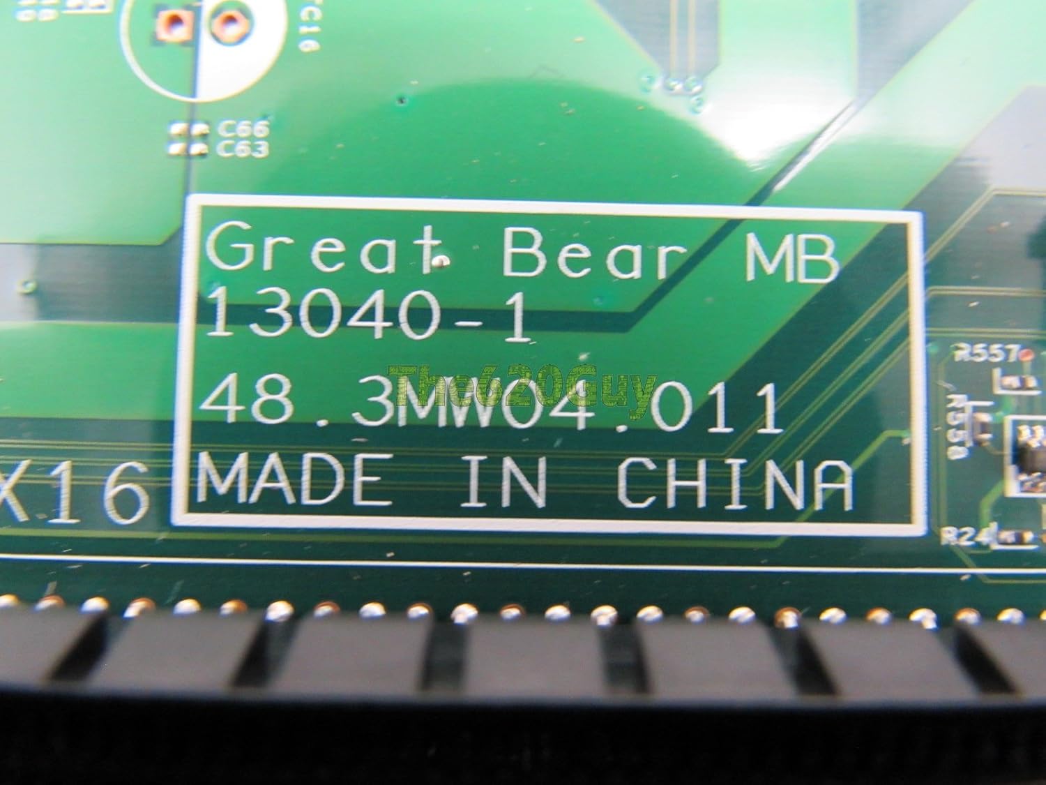
Figure 7.1: Close-up of a label on the motherboard, indicating manufacturing details and model identifiers such as 'Great Bear MB 13040-1 48.3MW04.011 MADE IN CHINA'.
8. Warranty and Support
For warranty information and technical support, please refer to the documentation provided with your Dell Inspiron 3847 MT system or visit the official Dell support website. Dell provides comprehensive support resources, including drivers, manuals, and troubleshooting guides for their products.
When contacting support, please have your system's service tag and the motherboard model number (88DT1 or 088DT1) readily available.


