1. Introduction
This manual provides essential instructions for the safe and efficient operation, maintenance, and troubleshooting of your CGOLDENWALL 1200W Electric Hydraulic Hole Puncher, Model JP-20. Please read this manual thoroughly before operating the tool to ensure proper usage and to prevent injury or damage.
1.1 Safety Information
Always observe basic safety precautions to reduce the risk of fire, electric shock, and personal injury. Keep the work area clean and well-lit. Do not operate power tools in explosive atmospheres, such as in the presence of flammable liquids, gases, or dust. Keep children and bystanders away while operating a power tool.
- Wear appropriate personal protective equipment (PPE), including safety glasses, gloves, and hearing protection.
- Ensure the tool is properly grounded and connected to a suitable power supply (110V).
- Inspect the tool and power cord for damage before each use. Do not use if damaged.
- Keep hands and fingers clear of the punching area during operation.
- Secure the workpiece firmly before punching.
- Do not overload the tool or attempt to punch materials beyond its specified capacity.
- Disconnect the power supply before performing any maintenance, changing dies, or when the tool is not in use.
2. Product Overview and Components
The CGOLDENWALL JP-20 is an electric hydraulic hole puncher designed for creating precise holes in various metal plates. It features a powerful 1200W motor for fast and efficient punching.

Figure 2.1: CGOLDENWALL JP-20 Hydraulic Hole Puncher with included dies and examples of punched materials.
2.1 Main Components

Figure 2.2: Key components of the CGOLDENWALL JP-20 Hydraulic Hole Puncher.
- Operating Handle: Ergonomically designed for control during operation.
- Refueling Hole: Used for adding hydraulic oil to the system.
- Unique Safety Valve: Ensures safe operation and pressure release.
- Power Cable: Connects the tool to the electrical supply.
- Support Base (Removable): Provides stability for stationary work.
- Punching Head: Houses the punch and die mechanism.
- Switch Key: Activates the punching mechanism.
2.2 What's in the Box

Figure 2.3: Included items in the CGOLDENWALL JP-20 package.
- CGOLDENWALL JP-20 Punching Machine
- Large Wrench
- Hex Wrench + Screws
- Molds (Dies): φ6.5mm, φ9mm, φ13mm, φ17mm, φ20.5mm
3. Specifications

Figure 3.1: Detailed specifications and dimensions.
| Parameter | Value |
|---|---|
| Model | JP-20 |
| Voltage | 110V |
| Wattage | 1200W |
| Output | 10T |
| Punch Speed | 2-3 seconds |
| Deep Throat | 40mm |
| Iron/Steel Plate Thickness | ≤6mm (0.23 Inch) |
| Copper/Aluminum Plate Thickness | ≤8mm (0.31 Inch) |
| Angle Iron Thickness | ≤6mm (0.23 Inch) |
| Standard Punch Dies | φ6.5mm, φ9mm, φ13mm, φ17mm, φ20.5mm |
| Product Dimensions | Approximately 19.69 x 7.68 x 3.94 inches |
| Item Weight | 12 Kilograms (26.46 Pounds) |
| Material | Alloy Steel, Aluminum |
4. Setup
4.1 Attaching the Support Base
For stable operation on a workbench, attach the removable support base to the main unit using the provided screws and hex wrench. Ensure it is securely fastened.
4.2 Installing Punch Dies

Figure 4.1: Standard punch dies included with the tool.
- Select the Correct Die: Choose the punch and die set that matches the desired hole size.
- Ensure Power Off: Disconnect the tool from the power supply before changing dies.
- Insert Die: Carefully insert the selected die into the punching head. Refer to the diagram for proper orientation.
- Secure Die: Use the provided wrench to tighten and secure the die in place. Ensure it is firmly seated to prevent movement during operation.
5. Operating Instructions
The CGOLDENWALL JP-20 offers two working modes: stationary with the base or handheld with the auxiliary handle. Always ensure the workpiece is stable and secured.

Figure 5.1: The hydraulic puncher in operation, demonstrating its speed.
5.1 Punching Procedure
- Prepare Workpiece: Mark the desired punching location on the metal plate. Ensure the material thickness is within the tool's specifications (e.g., Iron/steel plate ≤6mm, Copper/aluminum plate ≤8mm).
- Position Workpiece: Place the workpiece under the punch, aligning the marked spot with the center of the punch. The tool is designed for accurate positioning without offset.
- Connect Power: Plug the power cable into a suitable 110V electrical outlet.
- Initiate Punch: Press the switch key (trigger) to activate the hydraulic punching mechanism. The punch will rapidly descend, create the hole, and retract. The punching speed is approximately 2-3 seconds.
- Release Switch: Release the switch key once the punch has completed its cycle.
- Remove Workpiece: Carefully remove the punched workpiece.
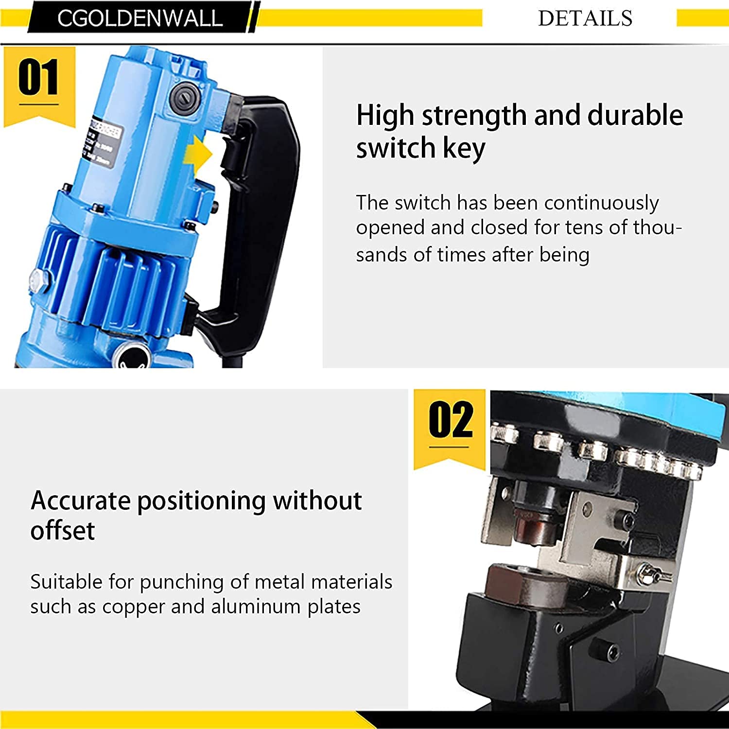
Figure 5.2: Details of the durable switch key and precise punching mechanism.
5.2 Material Compatibility
The tool is suitable for punching holes in:
- Iron/Steel Plate: Up to 6mm thickness
- Copper/Aluminum Plate: Up to 8mm thickness
- Angle Iron: Up to 6mm thickness

Figure 5.3: Application example and punching range for various materials.
6. Maintenance
Regular maintenance ensures the longevity and optimal performance of your hydraulic hole puncher. Always disconnect the power before performing any maintenance.
6.1 Cleaning
- After each use, clean the punching head and dies to remove metal shavings and debris.
- Use a dry cloth or soft brush. Do not use harsh chemicals or solvents.
6.2 Hydraulic Oil Level Check and Refueling
Periodically check the hydraulic oil level. If the level is low, refill through the designated refueling hole. Use only recommended hydraulic oil for this tool.
- Locate the refueling hole (refer to Figure 2.2).
- Unscrew the cap and check the oil level.
- If necessary, add hydraulic oil until the appropriate level is reached.
- Securely replace the cap.
6.3 Die Inspection
Inspect the punch and die for wear or damage. Worn dies can lead to poor punching quality and increased strain on the tool. Replace worn dies promptly.
7. Troubleshooting
This section addresses common issues you might encounter with your hydraulic hole puncher.
| Problem | Possible Cause | Solution |
|---|---|---|
| Tool does not start | No power supply; Damaged power cord; Faulty switch | Check power connection and outlet; Inspect power cord for damage; Contact customer support if switch is faulty. |
| Punching is slow or weak | Low hydraulic oil level; Air in hydraulic system; Worn punch/die; Material too thick | Check and refill hydraulic oil; Bleed air from the system (refer to advanced maintenance); Replace punch/die; Ensure material is within specifications. |
| Poor hole quality (burrs, uneven edges) | Worn punch/die; Incorrect die size for material; Workpiece not secured | Replace punch/die; Use appropriate die for material and thickness; Secure workpiece firmly. |
| Tool overheats | Continuous operation; Overloading; Insufficient ventilation | Allow tool to cool down; Do not exceed material thickness limits; Ensure proper airflow around the motor. |
If you encounter issues not listed here or if the suggested solutions do not resolve the problem, please contact CGOLDENWALL customer support.
8. Warranty and Customer Support
For warranty information, please refer to the documentation provided with your purchase or contact CGOLDENWALL directly. Keep your purchase receipt as proof of purchase.
8.1 Contact Information
For technical assistance, parts, or service, please contact CGOLDENWALL customer support through their official website or the retailer where the product was purchased.
You can visit the CGOLDENWALL Store on Amazon for more information or to find contact details.


