
1. Introduction
The Tekpower TP12003D is a professional DC regulated linear power supply designed for various applications requiring a stable and adjustable power source. This unit provides continuously adjustable output voltage from 0 to 120V DC and current from 0 to 3A. It features large LCD displays for accurate voltage and current readings and includes built-in overload protection.
This manual provides essential information for the safe and efficient operation, setup, maintenance, and troubleshooting of your TP12003D power supply. Please read it thoroughly before using the device.
2. Safety Information
WARNING: Failure to follow these safety instructions may result in electric shock, fire, or personal injury.
- Ensure the input voltage matches the specified rating (110V AC) before connecting the power supply.
- Do not operate the power supply in wet or damp conditions.
- Do not open the casing of the power supply. There are no user-serviceable parts inside. Refer all servicing to qualified personnel.
- Always disconnect the power cord from the AC outlet before performing any maintenance or if the unit will be unused for an extended period.
- Ensure proper ventilation around the unit to prevent overheating. Do not block ventilation openings.
- Use only the provided power cord and accessories.
- Avoid short-circuiting the output terminals.
3. Package Contents
Verify that all items listed below are present in your package:
- Tekpower TP12003D DC Regulated Power Supply Unit
- Alligator Clip Probe
- User Manual (this document)
- Power Cord

Figure 3.1: Tekpower TP12003D unit with power cord and alligator clip probes.
4. Product Overview
4.1 Front Panel

Figure 4.1: Front Panel Layout
- Voltage Display (V): Digital LCD display showing the output voltage.
- Current Display (A): Digital LCD display showing the output current.
- Voltage Adjustment Knob: Used to adjust the output voltage.
- Current Adjustment Knob: Used to adjust the current limit.
- Output Terminals (+/-): Main output terminals for connecting loads. Red for positive, Black for negative.
- Sampling Terminals: Additional terminals for remote sensing or specific applications.
- Power Switch: ON/OFF switch for the unit.
- Output ON/OFF Button: Controls the output power to the terminals independently of the main power switch.
4.2 Rear Panel
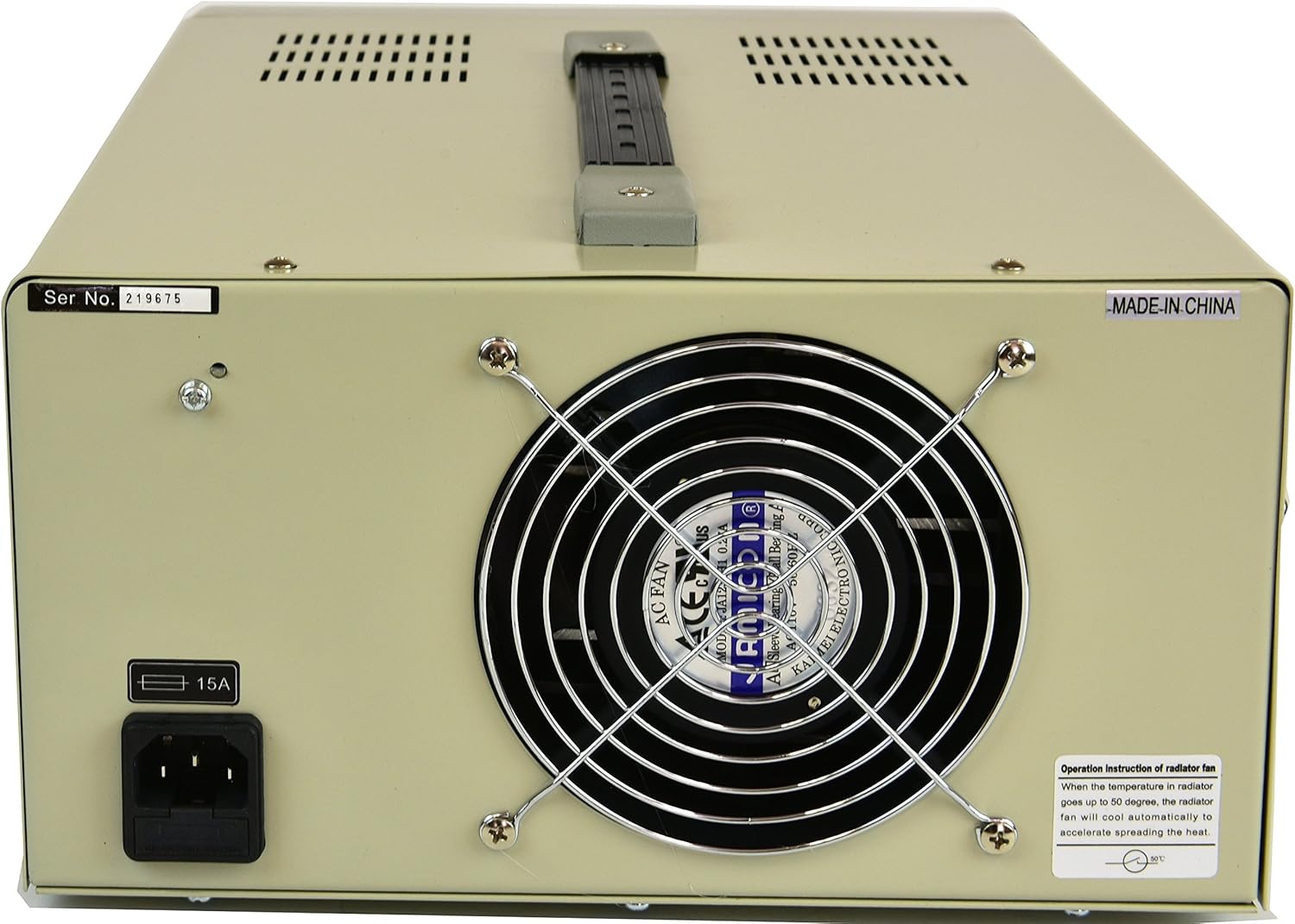
Figure 4.2: Rear Panel Layout
- AC Power Input: Connector for the main power cord.
- Fuse Holder: Contains the main protective fuse (8A).
- Cooling Fan: Automatically activates to dissipate heat during operation.
5. Setup
- Unpacking: Carefully remove the power supply from its packaging. Retain the packaging for future transport or storage.
- Placement: Place the unit on a stable, level surface with adequate ventilation. Ensure there is at least 10 cm (4 inches) of clear space around all sides, especially the rear cooling fan. Avoid placing it near heat sources or in direct sunlight.
- Power Connection:
- Ensure the power switch on the front panel is in the OFF position.
- Connect the provided power cord to the AC Power Input on the rear panel.
- Plug the other end of the power cord into a grounded 110V AC outlet.
- Initial Check: Before connecting any load, turn the power switch ON. The displays should illuminate. Verify that the voltage and current displays show readings (initially 0V and 0A or a small residual value).
6. Operating Instructions
6.1 Setting Voltage and Current Limits
- Ensure the power supply is ON but the output is OFF (Output ON/OFF button).
- Turn the Voltage Adjustment Knob clockwise to increase the voltage or counter-clockwise to decrease it. Observe the Voltage Display.
- Turn the Current Adjustment Knob clockwise to increase the current limit or counter-clockwise to decrease it. This sets the maximum current the supply will deliver.
- For precise settings, adjust the coarse knob first, then fine-tune with the fine adjustment knob (if available, or use small turns for precision).
6.2 Connecting a Load
- Ensure the power supply output is OFF.
- Connect the positive (+) terminal of your load to the red output terminal of the power supply.
- Connect the negative (-) terminal of your load to the black output terminal of the power supply.
- Double-check all connections for polarity and security.
6.3 Applying Power to the Load
- After setting the desired voltage and current limits and connecting the load, press the Output ON/OFF button to enable the output.
- Observe the Voltage and Current Displays. The voltage should stabilize at the set value, and the current display will show the actual current drawn by the load (up to the set current limit).
- If the load draws more current than the set limit, the power supply will enter constant current (CC) mode, and the current display will show the set limit. The voltage will drop to maintain this current.
- To turn off the output, press the Output ON/OFF button again.
7. Maintenance
- Cleaning: Disconnect the power supply from the AC outlet before cleaning. Use a soft, dry cloth to wipe the exterior. Do not use abrasive cleaners or solvents.
- Ventilation: Regularly check that the ventilation openings and cooling fan are free from dust and obstructions. Use compressed air to gently clear dust if necessary.
- Fuse Replacement: If the power supply does not turn on, check the fuse located on the rear panel.
- Disconnect the power cord.
- Unscrew the fuse holder cap.
- Replace the fuse with one of the same type and rating (8A).
- Screw the cap back on securely.
- Storage: When not in use for extended periods, store the power supply in a dry, dust-free environment.
8. Troubleshooting
| Problem | Possible Cause | Solution |
|---|---|---|
| No power, displays off. | Power cord not connected, AC outlet faulty, main power switch off, blown fuse. | Check power cord connection. Test AC outlet. Ensure power switch is ON. Check and replace fuse if necessary (refer to Maintenance section). |
| Output voltage is 0V or lower than set, current display shows set limit (CC mode). | Load resistance is too low, drawing more current than the set limit. | Increase the current limit using the Current Adjustment Knob, or reduce the load. Ensure the load is appropriate for the power supply's rating. |
| Output voltage is unstable or fluctuating. | Loose connections, faulty load, internal issue. | Check all output connections. Test with a different load. If the problem persists, contact customer support. |
| Unit overheats. | Blocked ventilation, excessive load, prolonged operation at high power. | Ensure ventilation openings are clear. Reduce load or operating time. Allow the unit to cool down. |
9. Specifications
| Model | TP12003D |
| Input Voltage | 110V AC |
| Output Voltage | 0-120V DC (Adjustable) |
| Output Current | 0-3A (Adjustable) |
| Display | Large LCD (3 1/2 Digits) for Voltage and Current |
| Technology | SMD Technology, Linear Transformer Type |
| Protection | Overload Protection Circuit, 8A Fuse Protection |
| Dimensions (L x W x H) | 11 x 6 x 14 inches (approx.) |
| Weight | 25.7 lbs (approx.) |
| Cooling Method | Air (Internal Fan) |
10. Warranty
The Tekpower TP12003D DC Adjustable Linear Power Supply comes with a 1-year USA warranty from the date of purchase. This warranty covers defects in materials and workmanship under normal use. It does not cover damage caused by misuse, accident, unauthorized modification, or improper operation. Please retain your proof of purchase for warranty claims.
11. Customer Support
For technical assistance, troubleshooting beyond this manual, or warranty inquiries, please contact Tekpower customer support. Refer to the contact information provided with your purchase or visit the official Tekpower website for the most up-to-date support details.
Manufacturer: TekPower


