
1. Introduction
This manual provides comprehensive instructions for the ONKYOU PWM DC Motor Speed Controller Module. This device is designed for stepless speed regulation of DC motors, offering precise control over a wide voltage and power range. Please read this manual thoroughly before installation and operation to ensure safe and efficient use.
2. Safety Information
- Always disconnect power before making any wiring connections or adjustments.
- Ensure that the input voltage and current ratings of the module match your power supply and motor requirements. The module supports DC 6V-90V, up to 15A and 1000W.
- Avoid short circuits during wiring. Incorrect wiring can damage the module and connected components.
- Install the module in a well-ventilated area to prevent overheating. The heatsinks on the module are crucial for heat dissipation.
- Do not exceed the maximum current or power ratings. Overloading can lead to component failure and potential fire hazards.
- Keep the module away from moisture, dust, and corrosive substances.
- This product is intended for use by individuals familiar with basic electrical principles and safety practices.
3. Product Features
- Wide Voltage Range: Operates with DC input voltages from 6V to 90V.
- High Power Capacity: Supports up to 15A continuous current and 1000W power output.
- PWM Technology: Utilizes Pulse Width Modulation for efficient and stable motor speed control.
- Stepless Speed Adjustment: Allows for smooth and continuous speed variation.
- 0-5V PLC Control: Compatible with external 0-5V PLC signals for automated speed control.
- Integrated Fuse: Includes a 15A fuse for overcurrent protection.
- Robust Design: Equipped with multiple heatsinks for effective thermal management.
4. Specifications
| Parameter | Value |
|---|---|
| Input Voltage | DC 6V - 90V |
| Maximum Continuous Current | 15A |
| Maximum Power | 1000W |
| Control Voltage (External) | 0-5V PLC |
| Product Weight | 96 g |
| Dimensions (approx.) | 10.9 x 8 x 4.2 cm |
5. Setup and Wiring
Follow these steps for proper installation and wiring of the speed controller module.
- Power Off: Ensure all power sources are disconnected before beginning.
- Identify Terminals: The module has clearly labeled terminals for power input, motor output, and control input.
- Connect Power Input: Connect your DC power supply (6V-90V) to the DC 6V-90V terminals. Ensure correct polarity: positive to '+' and negative to '-'.
- Connect Motor: Connect your DC motor to the Motor terminals. The polarity for the motor connection can be reversed to change the motor's direction of rotation.
- Optional 0-5V PLC Control: If using an external PLC for speed control, connect its 0-5V output to the designated control input terminals. If not using external control, the onboard potentiometer will be used for speed adjustment.
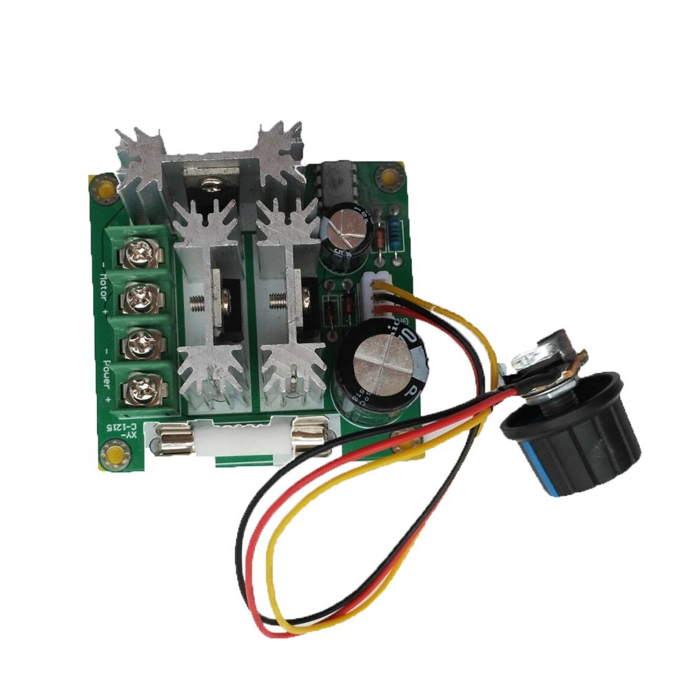
Figure 1: Basic Wiring Diagram. This image illustrates how to connect the DC power input and the DC motor to the speed controller module. The input voltage range (DC 6V-90V) and maximum current (15A) are indicated.
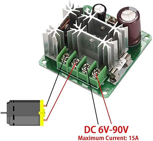
Figure 2: Module Overview. A detailed view of the speed controller module, highlighting the input/output terminals, potentiometer, and protective fuse.
6. Operating Instructions
Once the module is correctly wired, follow these steps to operate the motor speed controller:
- Power On: Apply power to the DC 6V-90V input terminals.
- Adjust Speed (Onboard Potentiometer): If not using external PLC control, rotate the potentiometer knob on the module to adjust the motor speed. Turning the knob clockwise typically increases speed, while counter-clockwise decreases it.
- Adjust Speed (0-5V PLC Control): If an external 0-5V PLC signal is connected, the motor speed will be controlled by the voltage level provided by the PLC. A 0V input will result in minimum speed (or off), and a 5V input will result in maximum speed.
- Monitor Performance: Observe the motor's operation. Ensure it runs smoothly without excessive noise or heat.
- Power Off: Disconnect the power supply when the motor is not in use.
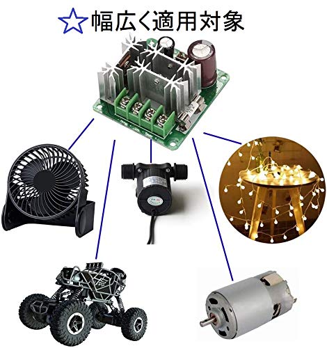
Figure 3: Application Examples. This image demonstrates various devices that can be controlled by the PWM module, such as fans, pumps, and other DC motors.
7. Maintenance
Regular maintenance helps ensure the longevity and reliable operation of your speed controller module.
- Cleaning: Periodically clean the module to remove dust and debris, especially from the heatsinks, to maintain optimal cooling. Use a soft, dry brush or compressed air.
- Connection Checks: Regularly inspect all wiring connections to ensure they are secure and free from corrosion. Loose connections can cause intermittent operation or damage.
- Thermal Management: Ensure the module has adequate airflow. If operating under heavy loads, consider additional cooling measures if the module becomes excessively hot.
- Fuse Replacement: The module is equipped with a 15A fuse for protection. If the fuse blows, disconnect power, identify and resolve the cause of the overcurrent, and replace it with a fuse of the same rating (15A).

Figure 4: Integrated Installation Example. This image shows the speed controller module integrated into a fan system, demonstrating a practical application and the importance of proper mounting and ventilation.
8. Troubleshooting
If you encounter issues with your ONKYOU PWM DC Motor Speed Controller, refer to the following troubleshooting guide:
| Problem | Possible Cause | Solution |
|---|---|---|
| Motor does not run. |
|
|
| Motor speed is inconsistent or uncontrollable. |
|
|
| Module overheats during operation. |
|
|
| Fuse blows repeatedly. |
|
|
9. Warranty and Support
Specific warranty information for this ONKYOU product is not provided in the available documentation. For any technical support or warranty inquiries, please refer to the retailer or the official Onkyo support channels where the product was purchased.

Figure 5: Product Packaging. The module is typically shipped in a compact cardboard box with the ONKYOU branding.