Introduction
This manual provides detailed instructions for the safe and effective use of the BSIDE ADM02 Auto Ranging Digital Multimeter. This handheld, battery-operated DMM offers multiple functions for various electrical measurements.
Designed to meet IEC61010-1 & CAT II 600V overvoltage category and double insulation standards, the ADM02 features a robust holster for enhanced drop resistance. It is an ideal general measurement tool for schools, laboratories, factories, and other professional or educational environments.

Figure 1: Front view of the BSIDE ADM02 Digital Multimeter with its display and function dial.
Safety Information
WARNING: To avoid electrical shock or personal injury, please read and understand all safety information before using this multimeter.
General Safety Rules
- Always ensure the test leads are properly connected and the function switch is set to the correct range before making any measurements.
- Do not apply more than the rated voltage, as marked on the meter, between the terminals or between any terminal and earth ground.
- Use extreme caution when working with voltages above 30V AC RMS, 42V peak, or 60V DC. These voltages pose a shock hazard.
- Disconnect the circuit power and discharge all high-voltage capacitors before testing resistance, continuity, or diodes.
- Always remove the test leads from the circuit before changing the function switch position.
- Do not use the meter if it appears damaged or if the insulation on the test leads is compromised.
- Replace the battery when the low battery indicator appears to ensure accurate readings.
- To prevent fire, install fuse with amp/volt ratings shown on the back of the device.
Safety Class
This device complies with IEC 61010-1, CAT II 600V safety standards.
Product Features
- 2000 counts Auto Ranging Digital Multimeter (DMM).
- 3 1/2 digit LCD display with backlight for clear readings.
- Full overload protection and dual insulation protection for enhanced safety.
- Capable of measuring DC/AC voltage, DC/AC current, resistance, temperature, and performing diode & continuity checks.
- Data Hold function to freeze the displayed reading.
- Max value hold function to capture the maximum measured value.
- Low battery indication for timely battery replacement.
- Auto power off feature to conserve battery life.
- Compact dimensions: 140 x 67 x 30mm.
- Operating Temperature: 0 ~ 40 ℃ (32 ~ 104 ℉) & <80% RH.
- Storage Temperature: -10 ~ 50 ℃ (14 ~ 122 ℉) & <70% RH.
Package Contents
Please check the package for the following items:
- 1 x ADM02 Multimeter
- 1 x Test leads (one red, one black)
- 1 x K-type temperature probe
- 1 x User's Manual

Figure 2: The BSIDE ADM02 Multimeter shown with its test leads, temperature probe, and user manual.
Setup
Battery Installation
The ADM02 Multimeter requires one 9V battery (6F22 or 1604A Type).
- Ensure the multimeter is turned OFF.
- Locate the battery compartment cover on the back of the unit.
- Use a screwdriver to remove the screw securing the battery cover.
- Gently lift the cover.
- Connect the 9V battery to the battery clip, observing correct polarity (+ and -).
- Place the battery into the compartment.
- Replace the battery cover and secure it with the screw.

Figure 3: Rear view of the multimeter showing the battery compartment and stand.
Connecting Test Leads
Insert the red test lead into the "VΩTemp mA" input jack and the black test lead into the "COM" (common) input jack for most voltage, resistance, temperature, and current measurements (up to 200mA).
For high current measurements (up to 10A), insert the red test lead into the "10A" input jack and the black test lead into the "COM" jack.

Figure 4: The multimeter with test leads properly connected to the input jacks.
Operating Instructions
General Operation
- Turn the rotary switch to the desired function (e.g., V~ for AC Voltage, V- for DC Voltage, Ω for Resistance, A~ for AC Current, A- for DC Current, Temp for Temperature, Diode/Continuity).
- Connect the test leads to the circuit or component under test.
- Read the measurement value on the LCD display.
Measuring DC/AC Voltage
- Set the rotary switch to the desired DC Voltage (V-) or AC Voltage (V~) range. The ADM02 is auto-ranging, so it will select the appropriate range automatically.
- Connect the red test lead to the positive side of the circuit and the black test lead to the negative side (for DC) or across the circuit (for AC).
- Read the voltage value.
Measuring DC/AC Current
- Set the rotary switch to the desired DC Current (A-) or AC Current (A~) range.
- For currents up to 200mA, ensure the red lead is in the "VΩTemp mA" jack. For currents up to 10A, move the red lead to the "10A" jack.
- Connect the multimeter in series with the circuit.
- Read the current value.
Measuring Resistance
- Set the rotary switch to the "Ω" range.
- Ensure the circuit is de-energized and all capacitors are discharged.
- Connect the test leads across the component to be measured.
- Read the resistance value.
Measuring Temperature
- Set the rotary switch to the "Temp" range.
- Connect the K-type temperature probe to the "VΩTemp mA" and "COM" jacks, observing polarity.
- Place the tip of the temperature probe on or near the object whose temperature is to be measured.
- Read the temperature value in Celsius or Fahrenheit.
Diode and Continuity Check
- Set the rotary switch to the "Diode/Continuity" range.
- For diode test: Connect the red lead to the anode and the black lead to the cathode of the diode. A forward voltage drop will be displayed. Reverse the leads; an open circuit (OL) should be displayed.
- For continuity test: Connect the test leads across the circuit or component. If continuity exists (resistance below approx. 50Ω), the buzzer will sound.
Data Hold Function
Press the "HOLD" button to freeze the current reading on the display. Press it again to release.
Max Value Hold Function
Press the "MAX" button to display and hold the maximum value measured since the function was activated. Press it again to exit.
Backlight Function
Press the backlight button (light bulb icon) to turn the display backlight ON or OFF.
Auto Power Off
The multimeter will automatically power off after approximately 15 minutes of inactivity to conserve battery life. To reactivate, turn the rotary switch to OFF and then back to the desired function, or press any button.
Maintenance
Cleaning
Periodically wipe the case with a damp cloth and mild detergent. Do not use abrasives or solvents.
Battery Replacement
When the low battery indicator appears on the display, replace the 9V battery as described in the "Battery Installation" section.
Fuse Replacement
If the current measurement function does not work, the fuse may need replacement.
WARNING: To avoid electrical shock, remove test leads before opening the battery cover.
The fuses are located inside the meter. Refer to the specifications for the correct fuse ratings (e.g., F 250mA/250V and F 10A/250V). Fuse replacement should only be performed by qualified personnel.
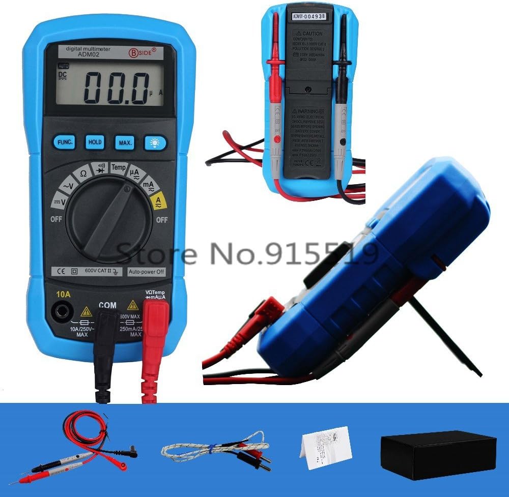
Figure 5: Rear view of the multimeter showing safety warnings and specifications.
Troubleshooting
| Problem | Possible Cause | Solution |
|---|---|---|
| Meter does not power on. | Dead or improperly installed battery. | Check battery installation; replace battery if necessary. |
| "OL" (Overload) displayed. | Input value exceeds selected range; open circuit (for resistance/continuity). | Select a higher range (if applicable); check circuit connection. |
| Inaccurate readings. | Low battery; incorrect function/range selected; poor test lead connection. | Replace battery; verify function/range; ensure secure connections. |
| No current measurement. | Blown fuse; incorrect test lead connection for current. | Check fuse (replace if necessary by qualified personnel); ensure red lead is in correct current jack (mA or 10A). |
If the problem persists after attempting these solutions, please contact customer support.
Specifications
| Parameter | Range | Accuracy |
|---|---|---|
| DC Voltage | 200mV/2V/20V/200V | ±(0.5%+2) |
| DC Voltage | 600V | ±(0.8%+2) |
| AC Voltage | 2V/20V/200V/600V | ±(1.0%+3) |
| DC Current | 200µA/2mA/20mA/200mA | ±(1.0%+3) |
| DC Current | 10A | ±(3.0%+3) |
| AC Current | 200µA/2mA/20mA/200mA | ±(1.2%+3) |
| AC Current | 10A | ±(3.0%+5) |
| Resistance | 200Ω/2kΩ/20kΩ/200kΩ/2MΩ | ±(0.8%+2) |
| Resistance | 20MΩ | ±(1.0%+2) |
| Temperature (℃) | -20℃~1000℃ | ±(3.0%+3) |
| Temperature (℉) | -0℉~1800℉ | ±(3.0%+3) |
General Specifications
- Display: 2000 counts, 3 1/2 digit LCD with backlight
- Power Supply: 9V Battery (6F22 or 1604A Type) x 1pc (not included)
- Operating Temperature & Humidity: 0 ~ 40℃ (32 ~ 104℉) & <80% RH
- Storage Temperature & Humidity: -10 ~ 50℃ (14 ~ 122℉) & <70% RH
- Safety Class: IEC 61010-1, CAT II 600V
- Dimensions (L x W x H): 140 x 67 x 30mm
- Weight: Approx. 140g (excluding battery)
Warranty and Support
For warranty information and technical support, please refer to the contact details provided with your purchase or visit the official BSIDE website. Keep your purchase receipt as proof of purchase.
Manufacturer: Bside
Date First Available: Dec 3 2016


