
HHIP 6060-0322
HHIP CPMT C6 Carbide Inserts User Manual
Model: 6060-0322
1. Introduction
This manual provides essential information for the proper use, installation, and maintenance of HHIP CPMT C6 Carbide Inserts. These inserts are designed for precision turning and finishing operations in various industrial applications.
Key features of the CPMT C6 Carbide Inserts include:
- 80° diamond shape with chip breaker.
- 11° relief angle for effective cutting.
- Suitable for both turning and finishing applications.
- ISO insert number: CPMT060204.
2. Product Overview
The HHIP CPMT C6 Carbide Insert is a precision cutting tool designed for optimal performance in machining operations. Its unique geometry and carbide material ensure durability and efficiency.
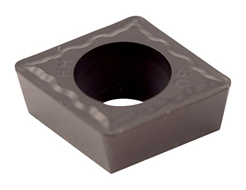
Figure 2.1: HHIP CPMT C6 Carbide Insert. This image shows the actual product, a dark grey, square-shaped carbide insert with a central hole and an 80-degree diamond shape.

Figure 2.2: Technical drawing illustrating the dimensions and angles of a CPMT insert, including the inscribed circle (I.C.), length (L), thickness (S), and corner radius (R).

Figure 2.3: A section from a carbide insert selection chart, specifically highlighting the CPMT 80° Black-Diamond Coated Positive Rake Carbide Inserts. This chart helps in identifying the specific insert type and its general characteristics.
The CPMT insert features an 80° diamond shape, which is common for turning and facing operations. The C6 grade carbide material provides excellent wear resistance and toughness for general purpose machining of various materials.
3. Setup & Installation
Proper installation of the carbide insert is crucial for optimal performance and tool life. Always ensure the tool holder is clean and free of debris before mounting the insert.
3.1 Tool Holder Compatibility
Ensure that the tool holder is compatible with CPMT style inserts. The insert's ISO designation (CPMT060204) provides specific details about its shape, size, and tolerance. Refer to the tool holder's specifications for proper matching.

Figure 3.1: Technical information for external turning toolholders, illustrating various clamping methods, insert shapes, and designation systems. This helps in selecting the correct tool holder for the CPMT insert.
3.2 Insert Mounting Procedure
- Cleanliness: Before installing, thoroughly clean the insert pocket of the tool holder to remove any chips, dust, or foreign particles. A clean seating surface ensures proper clamping and prevents premature insert failure.
- Positioning: Place the CPMT insert into the tool holder pocket, ensuring it sits flush and correctly oriented. The 80° diamond shape should align with the pocket's geometry.
- Clamping: Secure the insert using the appropriate clamping mechanism of your tool holder (e.g., screw, lever, or top clamp). Tighten the clamping screw to the manufacturer's recommended torque specifications. Overtightening can damage the insert or screw, while undertightening can lead to insert movement during machining.
- Inspection: After clamping, visually inspect the insert to ensure it is securely seated and there is no gap between the insert and the tool holder pocket.

Figure 3.2: Detailed charts explaining ANSI and ISO insert designation systems. This information is vital for understanding the specific characteristics and compatibility of the CPMT060204 insert.
4. Operating Instructions
The HHIP CPMT C6 Carbide Inserts are versatile for various turning and finishing operations. Adhering to proper operating parameters will maximize tool life and achieve desired surface finishes.
4.1 General Machining Guidelines
- Material Compatibility: C6 grade carbide is suitable for general purpose machining of steel, cast iron, and some non-ferrous materials. Refer to grade comparison charts for specific material recommendations.
- Cutting Parameters: Optimize cutting speed, feed rate, and depth of cut based on the workpiece material, machine rigidity, and desired surface finish. Start with manufacturer-recommended parameters and adjust as needed.
- Coolant Usage: Use appropriate cutting fluid to dissipate heat, lubricate the cutting zone, and evacuate chips. This helps extend insert life and improve surface quality.
- Chip Control: The integrated chip breaker on the CPMT insert is designed to manage chip formation effectively, preventing long, tangled chips that can interfere with the machining process.

Figure 4.1: Chart detailing various chip-breaker geometries and their recommended applications. The CPMT insert features a specific chip-breaker designed for optimal chip control during turning and finishing.
4.2 Turning and Finishing Applications
The 80° diamond shape and 11° relief angle make these inserts ideal for a range of operations:
- External Turning: Suitable for general turning of external diameters.
- Facing: Effective for machining flat faces perpendicular to the workpiece axis.
- Finishing: The sharp cutting edge and precise geometry contribute to excellent surface finishes, especially when using appropriate feed rates and depths of cut.
5. Maintenance
Proper maintenance extends the life of your carbide inserts and ensures consistent performance.
5.1 Cleaning and Storage
- Cleaning: After use, clean inserts to remove any adhering chips or coolant residue. Use a soft brush or compressed air. Avoid harsh chemicals that could damage the coating.
- Storage: Store inserts in their original packaging or in dedicated insert trays to prevent chipping or damage to the cutting edges. Keep them in a dry environment to prevent corrosion.
5.2 Inspection for Wear
Regularly inspect inserts for signs of wear or damage. Replace inserts when:
- Flank Wear: Excessive wear on the flank face behind the cutting edge.
- Cratering: Pitting or cratering on the rake face.
- Chipping/Breakage: Visible chips or fractures on the cutting edge.
- Built-Up Edge (BUE): Accumulation of workpiece material on the cutting edge, which can indicate incorrect cutting parameters or insufficient lubrication.
Timely replacement of worn inserts prevents damage to the workpiece, machine, and tool holder.
6. Troubleshooting
This section addresses common issues encountered during machining with carbide inserts and provides potential solutions.
| Problem | Possible Cause | Solution |
|---|---|---|
| Poor Surface Finish |
|
|
| Premature Insert Wear |
|
|
| Chip Control Issues |
|
|
7. Specifications
Detailed technical specifications for the HHIP CPMT C6 Carbide Insert (Model: 6060-0322).
| Attribute | Value |
|---|---|
| Brand | HHIP |
| Model Number | 6060-0322 |
| Material | Carbide (C6 Grade) |
| Insert Type | CPMT (80° Diamond) |
| ISO Insert Number | CPMT060204 |
| Inscribed Circle (I.C.) | 3/8 inch |
| Corner Radius (R) | 0.0315 inch |
| Relief Angle | 11° |
| Product Dimensions (L x W x H) | 7.62 x 2.54 x 15.24 cm (3 x 1 x 6 inches) |
| Item Weight | 22.5 grams |
| UPC | 769053061924 |

Figure 7.1: A comprehensive chart comparing different carbide grades, their properties, and recommended applications. This helps in understanding the C6 grade's characteristics.
8. Warranty & Support
Information regarding product warranty and customer support is typically provided by the point of purchase or the manufacturer.
8.1 Warranty Information
Specific warranty terms for HHIP products, including carbide inserts, are subject to the policies of the authorized distributor or retailer from whom the product was purchased. Please retain your proof of purchase for any warranty claims.
8.2 Customer Support
For technical assistance, product inquiries, or support regarding your HHIP CPMT C6 Carbide Inserts, please contact your supplier or the HHIP customer service department. Contact details can usually be found on the manufacturer's official website or through your product distributor.
Ask a question about this manual
Ask about setup, troubleshooting, compatibility, parts, safety, or missing instructions. Manuals+ will review the question and use this page’s manual context to help answer it.