
1. Introduction
This manual provides detailed instructions for the proper installation, operation, and maintenance of your Southwest Speed Wilwood Front Disc Brake Kit, Model 140-10740-R. This kit is designed for specific Chrysler, Dodge, and Plymouth B & E-Body vehicles from 1962-1972 that are equipped with drum spindles. Please read all instructions thoroughly before beginning installation to ensure safety and optimal performance.
2. Safety Information
- Professional Installation Recommended: Brake system installation requires specialized knowledge and tools. If you are not confident in your mechanical abilities, seek assistance from a qualified automotive technician.
- Read All Instructions: Ensure you understand each step before proceeding.
- Wear Safety Gear: Always wear appropriate personal protective equipment, including safety glasses, gloves, and hearing protection, during installation.
- Vehicle Support: Securely support the vehicle on jack stands on a level surface before working underneath it. Never rely solely on a jack.
- Brake Fluid: Brake fluid is corrosive. Avoid contact with skin and painted surfaces. Dispose of used brake fluid responsibly.
- Torque Specifications: Adhere strictly to all specified torque values for fasteners. Improperly torqued fasteners can lead to component failure.
3. Package Contents
Carefully unpack all components and verify that all parts listed below are present and undamaged. If any parts are missing or damaged, contact Southwest Speed customer support immediately.

Figure 3.1: Overview of all components included in the brake kit. This image displays two red Wilwood calipers, two brake rotors, two hub assemblies, brake pads, mounting brackets, and various bolts, washers, and bearings.
- Wilwood Red Calipers (2)
- 12-inch Brake Rotors (2)
- Hub Assemblies (2)
- Brake Pads (Set for 2 calipers)
- Caliper Mounting Brackets (2)
- Bearings and Seals (Set)
- Hardware Kit (Bolts, washers, nuts)
- Dust Caps
4. Setup and Installation
This section outlines the general steps for installing the front disc brake kit. Refer to the exploded view diagram for component identification and assembly order. Specific torque values and detailed procedures may vary slightly based on your vehicle's exact configuration; always consult a vehicle-specific service manual if available.
4.1. Preparation
- Park the vehicle on a level surface and engage the parking brake.
- Loosen the front wheel lug nuts.
- Raise the front of the vehicle using a floor jack and support it securely with jack stands.
- Remove the front wheels.
- Remove the existing drum brake components (drum, wheel cylinder, shoes, hardware, backing plate) from the spindle. Clean the spindle thoroughly.
4.2. Hub and Rotor Assembly
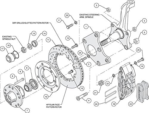
Figure 4.1: Exploded view diagram illustrating the assembly of the hub, rotor, and caliper onto the existing steering arm and spindle. Numbered components indicate the order and position of parts.
- Install the inner bearing and seal into the hub assembly.
- Mount the brake rotor to the hub using the provided hardware. Ensure the rotor is correctly oriented.
- Carefully slide the assembled hub and rotor onto the existing drum spindle.
- Install the outer bearing, washer, and spindle nut. Adjust the spindle nut to the manufacturer's specified preload, then install the cotter pin and dust cap.
4.3. Caliper Mounting
- Attach the caliper mounting bracket to the spindle using the provided bolts and washers. Torque to specifications.
- Mount the Wilwood caliper onto the bracket. Ensure the bleed screws are positioned at the top.
- Install the brake pads into the caliper.
- Connect the new brake lines to the calipers. Use appropriate fittings and ensure a secure, leak-free connection.
4.4. Bleeding the Brake System
After installation, the brake system must be properly bled to remove any air. Air in the brake lines can lead to a spongy pedal and reduced braking performance.
- Ensure the master cylinder is full of fresh, compatible brake fluid.
- Starting with the caliper furthest from the master cylinder, attach a clear hose to the bleed screw and submerge the other end in a container of brake fluid.
- Have an assistant slowly press the brake pedal down and hold it.
- Open the bleed screw until fluid and air bubbles stop flowing, then close the screw.
- Release the brake pedal.
- Repeat this process for each caliper until no air bubbles are visible.
- Maintain the master cylinder fluid level throughout the bleeding process.

Figure 4.2: Fully assembled Southwest Speed Wilwood front disc brake kit, showcasing the red 6-piston caliper, 12-inch rotor, and hub assembly.
4.5. Final Checks
- Double-check all fasteners for correct torque.
- Inspect all brake lines for leaks.
- Reinstall the wheels and torque lug nuts to vehicle manufacturer specifications.
- Lower the vehicle.
5. Operating and Break-in Procedure
Proper break-in of new brake pads and rotors is crucial for optimal performance and longevity. This process helps to transfer a thin, even layer of pad material onto the rotor surface.
- Initial Stops: Perform 10-15 moderate stops from approximately 30 mph (48 km/h) down to 5 mph (8 km/h). Allow a few seconds between stops for the brakes to cool slightly. Avoid coming to a complete stop during this phase.
- Cool Down: Drive for several minutes without using the brakes excessively to allow them to cool down completely.
- Avoid Hard Braking: For the first 200-300 miles (320-480 km) after installation, avoid sudden, hard braking or prolonged heavy braking. This allows the pads and rotors to fully seat.
- Monitor Performance: Pay attention to brake feel and noise during the break-in period. Any unusual sounds or sensations should be investigated.
6. Maintenance
Regular maintenance ensures the continued safety and performance of your disc brake system.
- Routine Inspection: Inspect brake pads, rotors, and calipers every 6,000-10,000 miles (10,000-16,000 km) or during tire rotations. Check for pad wear, rotor runout, and caliper leaks.
- Brake Fluid Level: Check the master cylinder brake fluid level regularly. A low level can indicate a leak or worn pads.
- Brake Fluid Replacement: Brake fluid absorbs moisture over time, which can reduce its boiling point and lead to corrosion. Consult your vehicle's service manual for recommended brake fluid flush intervals, typically every 2-3 years.
- Pad and Rotor Replacement: Replace brake pads when they reach their minimum thickness. Rotors should be replaced if they are below minimum thickness, warped, or severely grooved.
- Cleaning: Keep brake components free of excessive dirt, dust, and debris. Use a dedicated brake cleaner if necessary.
7. Troubleshooting
This section addresses common issues you might encounter with your disc brake system.
| Symptom | Possible Cause | Solution |
|---|---|---|
| Spongy Brake Pedal | Air in the brake lines, low brake fluid, faulty master cylinder | Bleed the brake system, check fluid level and leaks, inspect master cylinder |
| Brake Squeal/Noise | Worn pads, improper pad installation, glazed rotors, foreign material | Inspect and replace pads, ensure proper installation, clean or resurface rotors, check for debris |
| Vibration During Braking | Warped rotors, uneven pad wear, loose wheel bearings | Inspect and replace rotors, check pad wear, inspect and adjust wheel bearings |
| Pulling to One Side | Sticking caliper, uneven pad wear, contaminated brake fluid, alignment issue | Inspect and service calipers, check pad wear, flush brake fluid, check vehicle alignment |
| Hard Brake Pedal | Vacuum assist issue, seized caliper, restricted brake line | Check vacuum system, inspect and service calipers, check brake lines for obstructions |
8. Specifications
- Model Number: 140-10740-R
- Brand: Southwest Speed (featuring Wilwood components)
- Rotor Diameter: 12 inches
- Caliper Type: Multi-piston, Red finish
- Position: Front Axle
- Approximate Item Weight: 49 pounds
- Compatibility: 1962-1969 Chrysler, Dodge, Plymouth B-Body cars with drum spindles; 1970-1972 Chrysler, Dodge, Plymouth B & E-Body cars with drum spindles.
9. Wheel Clearance Diagram
It is critical to ensure adequate wheel clearance after installing the disc brake kit. Use the diagram below to verify that your wheels provide sufficient space for the caliper and rotor assembly. Insufficient clearance can lead to interference and unsafe operating conditions.

Figure 9.1: Detailed wheel clearance diagram for Kit P/N 140-10740, indicating the minimum required clearance for the caliper and the wheel mounting surface offset. Dimensions are provided in inches and millimeters.
10. Warranty and Support
For warranty information, technical support, or to inquire about replacement parts, please contact Southwest Speed customer service. Keep your purchase receipt and model number (140-10740-R) handy when contacting support.
Southwest Speed Customer Service: Refer to your purchase documentation or the official Southwest Speed website for current contact information.