1. Introduction
This manual provides essential instructions for the installation, operation, and maintenance of your Cata PCB Switch Unit, a genuine replacement part designed for various extractor hood models from B&Q, Cata, Designair, and Cooke & Lewis. Please read this manual thoroughly before installation and use to ensure proper function and safety.
2. Safety Information
- Professional Installation Recommended: Installation of this electrical component should ideally be performed by a qualified electrician or a competent person familiar with electrical appliance repair.
- Disconnect Power: Always ensure the main power supply to the extractor hood is disconnected at the circuit breaker before attempting any installation, maintenance, or repair. Failure to do so can result in electric shock or serious injury.
- Handle with Care: The PCB switch unit contains delicate electronic components. Handle it carefully to avoid damage.
- Correct Wiring: Ensure all wiring connections are correct and secure according to the original appliance's wiring diagram. Incorrect wiring can lead to malfunction or electrical hazards.
- Keep Dry: Do not expose the unit to moisture or liquids.
3. Product Overview
The Cata PCB Switch Unit is a replacement control board for extractor hoods, featuring multiple buttons for various functions such as fan speed control and lighting. It includes a wiring harness for connection to the main power supply and other components of the hood.

Figure 1: Cata PCB Switch Unit. This image shows the black rectangular control unit with a bundle of multi-colored wires emerging from one end, ready for connection.
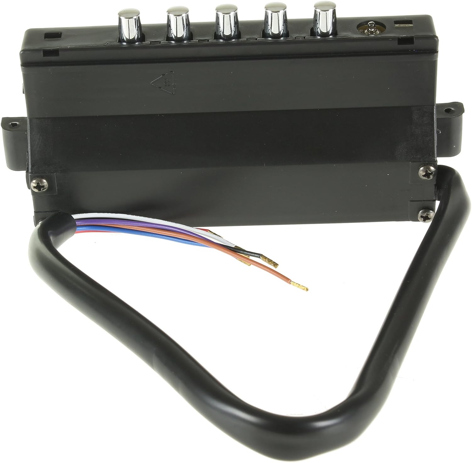
Figure 2: Top view of the control unit. This image displays the top surface of the black rectangular unit, featuring five distinct silver-colored push buttons for operational control.
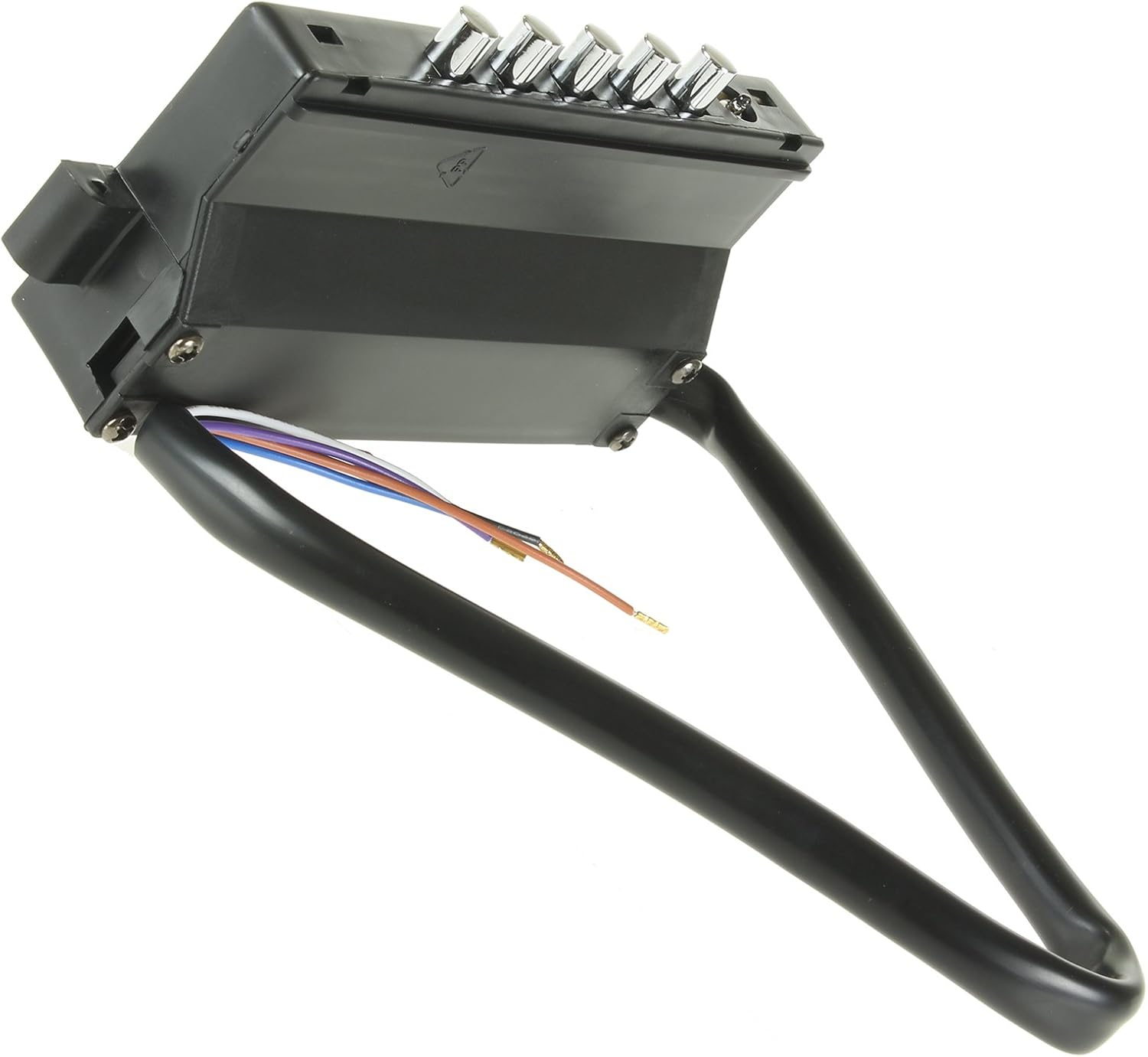
Figure 3: Angled view of the control unit. This image provides an angled perspective of the black unit, clearly showing the five silver control buttons and the attached wiring harness.
4. Compatible Models
This PCB Switch Unit is a genuine replacement part compatible with the following extractor hood models from B&Q, Cata, Designair, and Cooke & Lewis:
- APOLO 600
- APOLO 700
- APOLO 900
- CH60BK
- CH60SS
- CH70SS
- CH90SS
- CHK60BK
- CHK60SS
- CHK70BK
- CHK70SS
- CHK90BK
- CHK90SS
- CHKL60SS
Always verify the compatibility with your specific appliance model before proceeding with installation.
5. Setup and Installation
Important: Due to the electrical nature of this component, installation should only be performed by a qualified professional or someone with extensive experience in appliance repair and electrical work. Incorrect installation can lead to electrical hazards, damage to the appliance, or void the warranty.
5.1 Pre-Installation Steps
- Disconnect Power: Locate the circuit breaker for your kitchen or the specific extractor hood and switch off the power supply completely. Verify that the power is off using a voltage tester.
- Access the Existing Unit: Carefully remove any covers, filters, or panels necessary to access the existing PCB switch unit within your extractor hood. Refer to your extractor hood's original manual for specific disassembly instructions.
- Document Connections: Before disconnecting any wires, take clear photographs or make detailed diagrams of all existing wire connections to the old PCB unit. Note the color and position of each wire.
- Remove Old Unit: Disconnect all wires from the old PCB unit and carefully remove it from its mounting.
5.2 Installation of New Unit
- Mount New Unit: Position the new Cata PCB Switch Unit in the same location as the old unit. Secure it using the original mounting hardware, if applicable.
- Connect Wiring: Using your documented connections (photos/diagrams), carefully connect each wire from the extractor hood's harness to the corresponding terminal on the new PCB switch unit. Ensure all connections are firm and secure. Double-check all connections before proceeding.
- Secure Wires: Ensure that all wires are neatly routed and secured to prevent them from being pinched or damaged during reassembly.
- Reassemble Hood: Carefully reassemble any covers, filters, or panels that were removed. Ensure all components are properly seated and secured.
5.3 Post-Installation Check
- Restore Power: Once installation is complete and all covers are securely in place, restore power to the extractor hood at the circuit breaker.
- Test Functions: Test all functions of the extractor hood, including fan speeds and lighting, to ensure the new PCB switch unit is operating correctly.
6. Operating Instructions
The operation of the extractor hood is controlled via the buttons on the PCB Switch Unit. While specific functions may vary slightly depending on your extractor hood model, the general operation typically includes:
- Power On/Off: One button typically controls the main power to the fan.
- Fan Speed Control: Multiple buttons or a single button pressed repeatedly may cycle through different fan speeds (e.g., Low, Medium, High).
- Light Control: A dedicated button usually controls the extractor hood's lighting.
Refer to your original extractor hood's user manual for detailed instructions on specific button functions and operational modes.
7. Maintenance
The Cata PCB Switch Unit itself requires minimal maintenance. However, proper care of your extractor hood will ensure the longevity of all its components, including the switch unit.
- Cleaning: Ensure the exterior of the control panel is kept clean. Use a soft, damp cloth to wipe away grease and dust. Avoid abrasive cleaners or solvents that could damage the plastic or button markings.
- Filter Maintenance: Regularly clean or replace your extractor hood's grease filters as recommended by the hood's manufacturer. Clogged filters can reduce airflow and put strain on the fan motor and control unit.
- Avoid Liquid Exposure: Prevent liquids from spilling onto or entering the control panel area, as this can cause electrical shorts and damage the PCB.
8. Troubleshooting
If you experience issues after installing the new PCB Switch Unit, consider the following troubleshooting steps:
- No Power to Hood:
- Check the circuit breaker to ensure power is restored.
- Verify all wiring connections to the PCB unit are secure and correctly matched according to your documentation.
- Fan Not Working / Lights Not Turning On:
- Ensure the hood is receiving power.
- Re-check all wiring connections to the PCB unit, especially those related to the fan motor and light assembly.
- If only lights are not working, check the light bulbs themselves.
- Incorrect Fan Speed / Button Malfunction:
- Ensure the buttons are not stuck or obstructed.
- Verify that the correct PCB unit was installed for your specific hood model.
If troubleshooting steps do not resolve the issue, it is recommended to contact a qualified appliance technician or the manufacturer's support for further assistance.
9. Specifications
| Brand | Cata |
| Product Type | PCB Switch Unit for Extractor Hoods |
| Compatible Models | APOLO 600, APOLO 700, APOLO 900, CH60BK, CH60SS, CH70SS, CH90SS, CHK60BK, CHK60SS, CHK70BK, CHK70SS, CHK90BK, CHK90SS, CHKL60SS |
| Product Weight | 160 g |
| ASIN | B019OYMOJW |
| Manufacturer | CATA |
10. Warranty and Support
For information regarding warranty coverage, please refer to the original purchase documentation or contact the retailer where the product was acquired. As this is a replacement part, its warranty may be subject to the terms and conditions of the original appliance or the part itself.
For technical support or further inquiries, please contact Cata customer service or your appliance service provider.
You can visit the Cata Store on Amazon for more information on Cata products.


