1. Introduction
This manual provides essential information for the safe installation, operation, and maintenance of your EATON GFCI Self-Test 20A-125V Blank Face Receptacle, Model SGFD20W. This device is designed to protect against dangerous electrical shocks caused by ground faults by automatically interrupting the circuit.
2. Safety Information
WARNING: Risk of electric shock or electrocution. Installation must be performed by a qualified electrician in accordance with all national and local electrical codes.
- Always turn off power at the circuit breaker or fuse box before installing or servicing the GFCI device.
- Use only copper or copper-clad wire. Do not use aluminum wire.
- Ensure proper grounding.
- Do not install in circuits exceeding 125V AC.
- Test the GFCI monthly to ensure proper operation.
- This device is intended for indoor use or in suitable weatherproof enclosures for outdoor applications.
3. Product Overview
3.1. Components
- GFCI Blank Face Receptacle
- Color-matched standard size wallplate
- Mounting screws
3.2. Features
- Provides protection from dangerous electrical shocks caused by ground faults.
- Automatically self-tests periodically to ensure GFCI protection and continuous safety.
- Features an "End of Life" lockout and denial of power function, preventing reset if protection is compromised.
- Prevents power delivery if miswired during installation.
- Includes built-in indicator lights for quick notification of tripped or end-of-life conditions.
3.3. Product Diagram (Front View)
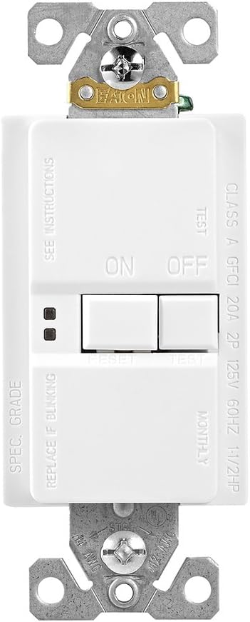
Image 1: Front view of the EATON GFCI Blank Face Receptacle, showing the ON/OFF buttons, TEST/RESET buttons, and indicator lights.
4. Setup and Installation
4.1. Tools Required
- Screwdriver (Phillips and/or Flathead)
- Wire strippers
- Voltage tester
- Electrical tape (optional)
4.2. Wiring Instructions
Before beginning, ensure power is OFF at the circuit breaker.
- Identify Wires: Carefully identify the LINE (incoming power) and LOAD (outgoing power to protected devices) wires. Also identify the neutral and ground wires.
- Strip Wires: Strip approximately 1/2 inch (12.7 mm) of insulation from each wire end.
- Connect LINE Wires: Connect the incoming hot (black) LINE wire to the brass LINE terminal screw and the incoming neutral (white) LINE wire to the silver LINE terminal screw. Tighten securely.
- Connect LOAD Wires (Optional): If protecting downstream receptacles or devices, connect the outgoing hot (black) LOAD wire to the brass LOAD terminal screw and the outgoing neutral (white) LOAD wire to the silver LOAD terminal screw. Remove the yellow tape covering the LOAD terminals before connecting.
- Connect Ground Wire: Connect the bare copper or green insulated ground wire to the green ground screw.
- Mount Device: Carefully fold wires into the electrical box and secure the GFCI device with the provided mounting screws.
- Install Wallplate: Attach the color-matched wallplate.
- Restore Power: Turn power back ON at the circuit breaker.
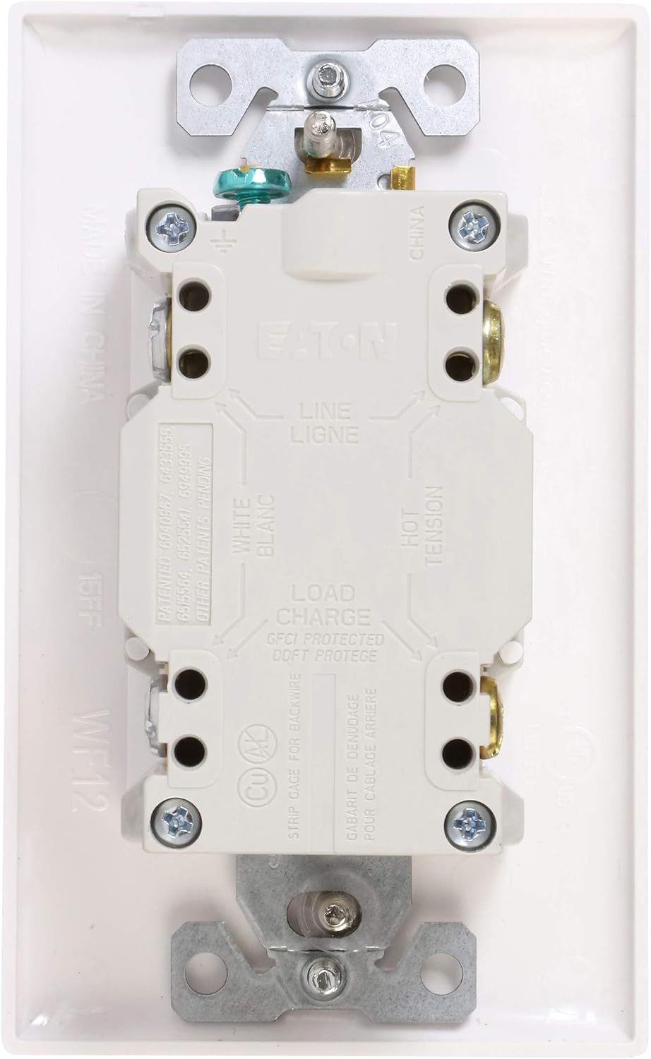
Image 2: Back view of the EATON GFCI Blank Face Receptacle, illustrating the LINE and LOAD terminal connections for proper wiring.
5. Operating Instructions
5.1. Initial Power-Up
After installation and restoring power, the GFCI device may be in a tripped state. Press the RESET button to restore power. The indicator light should turn green (or off, depending on model and status).
5.2. Self-Test Function
The EATON GFCI device automatically performs periodic self-tests to ensure its protective function is operational. During a self-test, the indicator light may briefly change color or flash. This is normal operation.
5.3. Manual Test and Reset
It is recommended to manually test the GFCI monthly.
- Press the TEST button. The GFCI should trip, and power to the protected circuit will be interrupted. The indicator light will typically turn red or off.
- Press the RESET button. Power should be restored, and the indicator light should return to its normal operating state (green or off).
- If the GFCI does not trip when the TEST button is pressed, or if it does not reset after tripping, it may be faulty or improperly wired. Discontinue use and consult a qualified electrician.
Image 3: Front view of the EATON GFCI Blank Face Receptacle, showing the location of the TEST and RESET buttons for manual operation.
6. Maintenance
6.1. Regular Checks
- Perform the manual test (Section 5.3) monthly.
- Visually inspect the device and wallplate for any signs of damage or wear.
- Keep the device clean and free from dust and debris.
6.2. End-of-Life Indication
The GFCI device is equipped with an "End of Life" (EOL) feature. If the device can no longer provide ground fault protection, it will deny power and prevent resetting. The indicator light will typically flash or remain red to signal this condition. If an EOL condition is indicated, the device must be replaced immediately.
7. Troubleshooting
| Problem | Possible Cause | Solution |
|---|---|---|
| GFCI will not reset. | No power to the GFCI, miswiring, ground fault present, or End-of-Life condition. | Check circuit breaker. Verify wiring (LINE/LOAD). Disconnect all loads to check for ground fault. If indicator light signals EOL, replace device. |
| GFCI trips frequently. | Ground fault in connected appliance/wiring, or overloaded circuit. | Unplug all appliances from the protected circuit and reset. If it holds, plug in appliances one by one to identify the faulty one. Reduce load on the circuit. |
| GFCI does not trip when TEST button is pressed. | Faulty GFCI device or miswiring. | Ensure power is on. Verify wiring. If problem persists, replace the GFCI device. |
| Indicator light is flashing or red. | GFCI tripped, or End-of-Life condition. | Press RESET. If it remains flashing or red and does not reset, the device has reached its End-of-Life and needs replacement. |
8. Specifications
| Specification | Value |
|---|---|
| Model Number | SGFD20W |
| Amperage Capacity | 20 Amps |
| Voltage | 125 Volts |
| Power Source | Wired Electric |
| Material | Thermoplastic |
| Color | White |
| Product Dimensions | 2.01 x 2.89 x 4.71 inches |
| Item Weight | 5.6 ounces |
| Manufacturer | EATON |
9. Warranty and Support
Eaton products are designed for reliability and performance. For specific warranty information, please refer to the documentation included with your purchase or visit the official Eaton website. For technical support or assistance, please contact Eaton customer service.
Eaton Website: www.eaton.com


