1. Introduction
This user manual provides detailed instructions for the safe and effective operation, maintenance, and troubleshooting of your Mastech M3900 Digital Multimeter. The M3900 is a versatile and reliable instrument designed for measuring DC/AC Voltage, DC/AC Current, Resistance, Diode, Continuity, and hFE. Please read this manual thoroughly before using the device to ensure proper functionality and safety.
2. Safety Information
WARNING: To avoid electric shock or personal injury, and to avoid damage to the meter or to the equipment under test, observe the following safety rules:
- Always ensure the function switch is in the correct position for the measurement being performed.
- Do not apply more than the rated voltage, as marked on the meter, between terminals or between any terminal and earth ground.
- Use extreme caution when working with voltages above 60V DC or 30V AC RMS. Such voltages pose a shock hazard.
- Disconnect the circuit power and discharge all high-voltage capacitors before testing resistance, continuity, or diodes.
- Do not use the meter if it appears damaged or if the insulation on the test leads is damaged.
- Remove the test leads from the meter before opening the battery cover or case.
- Replace the battery as soon as the low battery indicator appears to ensure accurate readings.
- The meter is designed for indoor use and complies with CE standards.
3. Product Overview
Familiarize yourself with the components of your Mastech M3900 Digital Multimeter.
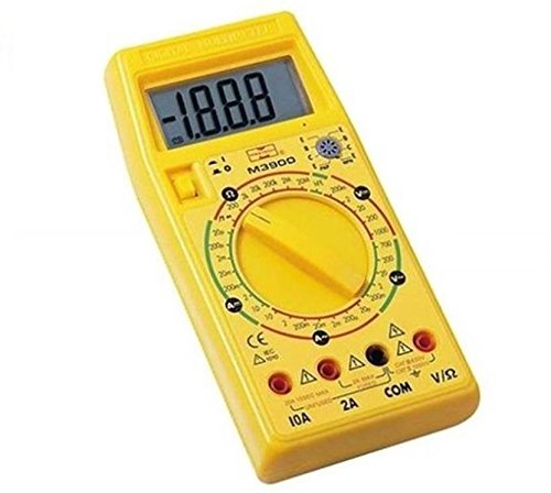
Figure 3.1: Front view of the Mastech M3900 Digital Multimeter, showing the large LCD display, rotary function switch, and input jacks.
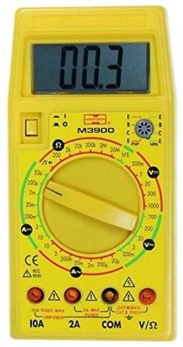
Figure 3.2: Close-up front view of the Mastech M3900 Digital Multimeter, highlighting the hFE transistor test socket and various measurement ranges.
Key Components:
- LCD Display: Shows measurement readings, units, and indicators.
- Rotary Function Switch: Used to select the desired measurement function and range.
- Input Jacks:
- COM (Common): Negative input for all measurements.
- V/?/mA: Positive input for Voltage, Resistance, Diode, Continuity, and small Current measurements (up to 200mA/2A depending on model).
- 10A: Positive input for high current measurements (up to 10A).
- hFE Socket: For testing the gain (hFE) of NPN and PNP transistors.
4. Setup
4.1 Battery Installation
- Ensure the multimeter is turned off and test leads are disconnected.
- Locate the battery compartment cover on the back of the meter.
- Unscrew the retaining screw(s) and remove the cover.
- Insert one 9V (6F22) battery, observing the correct polarity (+ and -).
- Replace the battery cover and secure it with the screw(s).
4.2 Test Lead Connection
Always connect the black test lead to the COM jack. Connect the red test lead to the appropriate jack based on the measurement:
- For Voltage, Resistance, Diode, Continuity, and small Current (mA/µA) measurements, connect the red lead to the V/?/mA jack.
- For high Current (10A) measurements, connect the red lead to the 10A jack.
5. Operating Instructions
Before making any measurement, ensure the test leads are correctly connected and the rotary switch is set to the desired function and range.
5.1 Measuring DC Voltage (DCV)
- Set the rotary switch to the desired DCV range (e.g., 200m, 2, 20, 200, 1000V). If the voltage is unknown, start with the highest range (1000V) and decrease as needed.
- Connect the red test lead to the positive (+) side of the circuit and the black test lead to the negative (-) side.
- Read the voltage value on the LCD display.
5.2 Measuring AC Voltage (ACV)
- Set the rotary switch to the desired ACV range (e.g., 200m, 2, 20, 200, 700V). If the voltage is unknown, start with the highest range (700V) and decrease as needed.
- Connect the test leads across the circuit or component to be measured.
- Read the voltage value on the LCD display.
5.3 Measuring DC Current (DCA)
CAUTION: Never connect the multimeter in parallel with a voltage source when measuring current. This can blow the fuse or damage the meter.
- Turn off the power to the circuit.
- Break the circuit at the point where you want to measure current.
- Set the rotary switch to the desired DCA range (e.g., 2µ, 200µ, 2m, 20m, 200m, 2A, 10A).
- Connect the meter in series with the circuit. For currents up to 2A, use the V/?/mA jack. For currents up to 10A, use the 10A jack.
- Apply power to the circuit and read the current value on the LCD display.
5.4 Measuring AC Current (ACA)
CAUTION: Never connect the multimeter in parallel with a voltage source when measuring current. This can blow the fuse or damage the meter.
- Turn off the power to the circuit.
- Break the circuit at the point where you want to measure current.
- Set the rotary switch to the desired ACA range (e.g., 20µ, 200µ, 2m, 20m, 200m, 2A, 10A).
- Connect the meter in series with the circuit. For currents up to 2A, use the V/?/mA jack. For currents up to 10A, use the 10A jack.
- Apply power to the circuit and read the current value on the LCD display.
5.5 Measuring Resistance (?)
CAUTION: Ensure the circuit is de-energized and all capacitors are discharged before measuring resistance.
- Set the rotary switch to the desired Resistance range (e.g., 200, 2k, 20k, 200k, 2M, 20M?).
- Connect the test leads across the component to be measured.
- Read the resistance value on the LCD display.
5.6 Continuity Test
- Set the rotary switch to the Continuity position (often indicated by a speaker icon).
- Connect the test leads across the circuit or component.
- If the resistance is below approximately 50?, the built-in buzzer will sound, indicating continuity.
5.7 Diode Check
- Set the rotary switch to the Diode position (often indicated by a diode symbol).
- Connect the red test lead to the anode and the black test lead to the cathode of the diode.
- The display will show the forward voltage drop (typically 0.5V to 0.8V for silicon diodes). Reversing the leads should show
Related Documents - M3900

MASTECH MY74 Digital Multimeter Quick Start Guide | Accurate Measurements
Get started quickly with the MASTECH MY74 Digital Multimeter. This guide covers setup, safety, and specifications for accurate voltage, current, resistance, capacitance, frequency, and temperature measurements.
MASTECH M300 Digital Multimeter User Manual
User manual for the MASTECH M300 digital multimeter, detailing its features, specifications, safety precautions, and operating instructions for measuring DC/AC voltage, DC current, resistance, continuity, and diode testing.
Mastech M838 Digital Multimeter Quick Start Guide
Concise guide to using the Mastech M838 digital multimeter, covering safety, specifications, and basic measurement procedures for voltage, current, resistance, and temperature.
MASTECH MS2016A Leakage Clamp Meter Operation Manual
Comprehensive operation manual for the MASTECH MS2016A AC Leakage Clamp Meter, covering safety information, specifications, operating guidance, maintenance, and accessories. Features include AC/DC voltage, resistance, capacitance, continuity, diode, and temperature measurements.
MASTECH MY-68 Digital Multimeter User Manual
Comprehensive user manual for the MASTECH MY-68 digital multimeter, covering specifications, safety instructions, operation, and maintenance.
MASTECH MS8211D Pen-type Digital Multimeter Quick Start Guide
A quick start guide for the MASTECH MS8211D pen-type digital multimeter, providing essential safety information, technical specifications, and basic operational instructions for voltage, current, resistance, and logic testing.Ask a question about this manual
Ask about setup, troubleshooting, compatibility, parts, safety, or missing instructions. Manuals+ will review the question and use this page’s manual context to help answer it.