1. Introduction
This manual provides detailed instructions for the installation, configuration, and maintenance of your GIGABYTE GA-Z170X-Gaming 7 motherboard. Designed for 6th and 7th Generation Intel Core Processors, this ATX motherboard features DDR4 memory support, dual M.2 slots, advanced audio, and high-speed USB 3.1 connectivity. Please read this manual thoroughly before beginning installation to ensure proper setup and operation.
2. Safety Information
Always observe the following safety precautions when handling computer components:
- Disconnect the power cord from the wall outlet before touching any components.
- Wear an anti-static wrist strap or frequently touch a grounded metal object to discharge static electricity.
- Handle components by their edges to avoid touching sensitive parts.
- Keep components away from moisture and extreme temperatures.
3. Package Contents
Verify that all items are present in your motherboard package:
- GIGABYTE GA-Z170X-Gaming 7 Motherboard
- User Manual and Driver CD
- SATA Cables
- I/O Shield
- M.2 Screws
- SLI Bridge (if included)
If any items are missing or damaged, contact your retailer.
4. Motherboard Layout and Components
Familiarize yourself with the key components and connectors on your GA-Z170X-Gaming 7 motherboard.
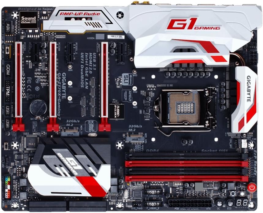
4.1. CPU Socket (LGA 1151)
The LGA 1151 socket supports 6th and 7th Generation Intel Core Processors. Ensure proper alignment and gentle placement of the CPU to avoid damaging the pins.
4.2. DDR4 DIMM Slots
The motherboard features four DDR4 DIMM slots, supporting up to 64GB of system memory. Install memory modules in matched pairs for optimal dual-channel performance. Refer to the motherboard's QVL (Qualified Vendor List) for compatible memory modules.
4.3. PCIe Expansion Slots
Multiple PCI Express slots are available for graphics cards and other expansion cards. The GA-Z170X-Gaming 7 supports NVIDIA SLI and AMD 3-Way CrossFire multi-graphics configurations.
4.4. M.2 Connectors
Two M.2 connectors are provided for high-speed NVMe SSDs, offering data transfer rates up to 32 Gb/s.
4.5. SATA Ports
The motherboard includes multiple SATA 6Gb/s ports for connecting traditional hard drives and SSDs.
4.6. Rear I/O Panel
The rear I/O panel provides various connectivity options, including USB 3.1 Type-C, USB 3.1, USB 3.0, HDMI, DisplayPort, Gigabit Ethernet (Killer E2400 and Intel GbE LAN), and audio jacks (Creative Sound Core3D).
5. Setup and Installation
5.1. CPU Installation
- Open the CPU socket lever.
- Carefully align the CPU with the socket, ensuring the gold triangle on the CPU matches the triangle on the socket.
- Gently place the CPU into the socket. Do not force it.
- Close the CPU socket lever to secure the CPU.
5.2. CPU Cooler Installation
Install your CPU cooler according to its manufacturer's instructions. Ensure proper thermal paste application and secure mounting for effective heat dissipation.
5.3. Memory (RAM) Installation
Open the clips on the DDR4 DIMM slots. Align the memory module with the slot, ensuring the notch on the module matches the key in the slot. Press down firmly on both ends of the module until the clips snap into place.
5.4. Graphics Card Installation
Insert your graphics card into the primary PCIe x16 slot. Ensure it is fully seated and secured with the retention clip and a case screw.
5.5. Storage Device Installation
For M.2 SSDs, insert the drive into the M.2 slot and secure it with the provided screw. For SATA drives, connect the SATA data cable to a motherboard SATA port and the power cable from your PSU to the drive.
5.6. Power Supply Connections
Connect the 24-pin ATX main power connector and the 8-pin ATX 12V CPU power connector from your power supply unit (PSU) to the corresponding ports on the motherboard.
5.7. Front Panel Connections
Connect the front panel headers (power button, reset button, HDD LED, power LED, front USB, front audio) to their respective pins on the motherboard. Refer to the motherboard layout diagram for exact pin locations.
6. Operating Instructions
6.1. Initial Boot-Up and BIOS Access
After assembling your system, power it on. Press the DEL key during the boot process to enter the UEFI BIOS Setup. The BIOS allows you to configure system settings, boot order, and enable features like XMP for memory overclocking.
6.2. BIOS Features
- UEFI Dual BIOS: Provides a backup BIOS in case the main BIOS becomes corrupted.
- Q-Flash Plus: Allows you to update the BIOS without installing a CPU, memory, or graphics card.
- Easy Tune: A utility within GIGABYTE APP Center for easy system tuning and overclocking.
6.3. Driver and Software Installation
After installing your operating system, install the necessary drivers from the provided CD or GIGABYTE's official website. This includes chipset, audio, LAN, and graphics drivers. Install the GIGABYTE APP Center for access to various utilities.
7. Maintenance
7.1. Cleaning
Regularly clean your computer's interior to prevent dust buildup, which can lead to overheating. Use compressed air to remove dust from fans, heatsinks, and other components. Ensure the system is powered off and unplugged before cleaning.
7.2. BIOS Updates
Periodically check GIGABYTE's website for BIOS updates. BIOS updates can improve system stability, add support for new hardware, or fix bugs. Follow the update instructions carefully to avoid damaging the motherboard.
7.3. Driver Updates
Keep your drivers updated to ensure optimal performance and compatibility with new software and hardware. Drivers can be downloaded from GIGABYTE's and component manufacturers' websites.
8. Troubleshooting
This section addresses common issues you might encounter:
- No Power: Check all power connections (24-pin, 8-pin CPU, GPU). Ensure the PSU is switched on.
- No Display: Verify that the monitor is connected to the graphics card (not the motherboard's integrated graphics ports, unless using integrated graphics). Reseat the graphics card and RAM modules.
- Memory Initialization Error (Code 55): This often indicates an issue with RAM or CPU seating. Reseat RAM modules and ensure the CPU is correctly installed in its socket.
- System Instability/Crashes: Check for overheating (monitor temperatures with software). Ensure drivers are up to date. Test memory modules individually.
- BIOS Reset: If system becomes unbootable due to incorrect BIOS settings, clear the CMOS by removing the CMOS battery for a few minutes or using the dedicated clear CMOS jumper/button.
9. Specifications
| Feature | Specification |
|---|---|
| CPU Socket | LGA 1151 |
| Compatible Processors | 6th/7th Generation Intel Core Processors |
| Chipset | Intel Z170 |
| Memory Slots | 4 x DDR4 DIMM sockets |
| Max Memory Capacity | 64 GB |
| Memory Speed (OC) | Up to 3866 MHz |
| PCIe Slots | Multiple PCIe x16 and x1 slots (SLI/CrossFire support) |
| M.2 Connectors | 2 x M.2 (PCIe Gen3 x4, up to 32 Gb/s) |
| SATA Ports | 6 x SATA 6Gb/s |
| USB Ports (Rear) | USB 3.1 Type-C, USB 3.1, USB 3.0, USB 2.0 |
| LAN | Killer E2400 Gigabit Ethernet + Intel GbE LAN |
| Audio | Creative Sound Core3D Quad-Core Audio |
| Form Factor | ATX (30.5cm x 24.4cm) |
10. Warranty and Support
GIGABYTE motherboards typically come with a manufacturer's warranty. Please refer to the warranty card included in your product packaging or visit the official GIGABYTE website for specific warranty terms and conditions applicable to your region.
For technical support, driver downloads, BIOS updates, and product registration, please visit the official GIGABYTE support website. You can also find FAQs and troubleshooting guides there.


