
1. Introduction
This manual provides detailed instructions for the installation, operation, and maintenance of the UHPPOTE Double Door Electromagnetic Lock, Model UT0531-280D. This device is designed to provide secure access control for various door types, offering a fail-safe locking mechanism with a 600lbs holding force per door.
Please read this manual thoroughly before installation and operation to ensure proper functionality and safety.
2. Product Features
- NC Mode Operation: The lock is engaged (locked) when power is supplied, and releases (unlocks) upon power loss, ensuring a fail-safe configuration.
- High Holding Force: Provides 600lbs (280kg) holding force per door, suitable for demanding security applications.
- Dual Voltage Compatibility: Operates with either 12VDC or 24VDC input, selectable for installation flexibility.
- Integrated Status LED: Features a dual-colored LED indicator (Red for locked, Green for unlocked) and a bond sensor to display the locking status of each door.
- Versatile Application: Compatible with various door types including wooden, glass, metal, and fireproof doors.
- Complete Mounting Hardware: Includes all necessary hardware for standard installations.
- Signal Output: Provides lock status signal (NO/NC/COM) for integration with access control systems.
3. Package Contents
Verify that all components are present before beginning installation:
- 1 x UHPPOTE Double Door Electromagnetic Lock Unit
- 2 x Armature Plates
- 1 x Installation Kit (includes screws, washers, and mounting accessories)
- 1 x User Manual (this document)
4. Specifications
| Feature | Specification |
|---|---|
| Model | UT0531-280D |
| Lock Body Dimensions (LxWxH) | 19-11/16" x 1-29/32" x 63/64" (500 x 48.5 x 25mm) |
| Armature Plate Dimensions (LxWxH) | 7-3/32" x 1-1/2" x 7/16" (180 x 38 x 11mm) |
| Holding Force | 600lbs x 2 (280kg x 2) |
| Input Voltage | 12VDC or 24VDC (selectable) |
| Current Draw | 12V/500mA x 2 or 24V/250mA x 2 |
| Suitable Door Types | Wooden door, glass door, metal door, fireproof door |
| Surface Temperature | Less than 122℉ (50℃) |
| Operating Temperature | 14℉ ~ 131℉ (-10℃ ~ 55℃) |
| Humidity | 0 ~ 90% (non-condensing) |
| Cover Finish | Anodized aluminum |
| Lock Finish | Zinc |
| Armature Plate Finish | Zinc |
| LED Indicator | Red (Locked), Green (Unlocked) |
| Signal Output | Lock signal (NO/NC/COM) |
| Item Weight | 9.26lbs (4.2kg) |
| Material | Aluminum |
| Control Method | Remote (via access control system) |
| Connectivity Protocol | Wired |
5. Safety Information
- Electrical Safety: Ensure all wiring is performed by a qualified professional and complies with local electrical codes. Disconnect power before installation or maintenance.
- Proper Voltage: Verify the correct voltage (12VDC or 24VDC) is selected and supplied to the lock. Incorrect voltage can damage the unit.
- Secure Mounting: The electromagnetic lock and armature plates must be securely mounted to prevent detachment and ensure proper holding force.
- Pinch Hazard: Keep hands and fingers clear of the lock and armature plate during operation to avoid pinching.
- Emergency Egress: Ensure that the access control system includes a reliable method for emergency egress, such as an exit button or integration with a fire alarm system.
6. Installation
6.1 Components Overview and Dimensions
Familiarize yourself with the components and their dimensions before installation.

Figure 1: Exploded view and dimensions of the electromagnetic lock components, including the electromagnet, armature plates, mounting plate, and various screws and washers.
6.2 Mounting the Lock
The electromagnetic lock is typically mounted on the door frame, and the armature plate is mounted on the door itself. Ensure the mounting surfaces are flat, clean, and strong enough to support the lock's weight and holding force.

Figure 2: Example of L-brackets, which may be used for specific mounting configurations (sold separately or included in some kits).
- Positioning: Determine the optimal position for the lock on the door frame and the armature plate on the door. For double doors, ensure both locks are aligned.
- Drilling: Mark and drill pilot holes for the mounting screws according to the lock and armature plate dimensions.
- Mounting the Electromagnet: Secure the main electromagnetic lock unit to the door frame using the provided long self-tapping screws. Ensure it is firmly attached.
- Mounting the Armature Plate: Attach the armature plate to the door using the armature screw, rubber washer, and steel washers. The armature plate should have a slight degree of movement to allow for proper alignment with the electromagnet.

Figure 3: General diagram showing the electromagnetic lock installed above a double door.
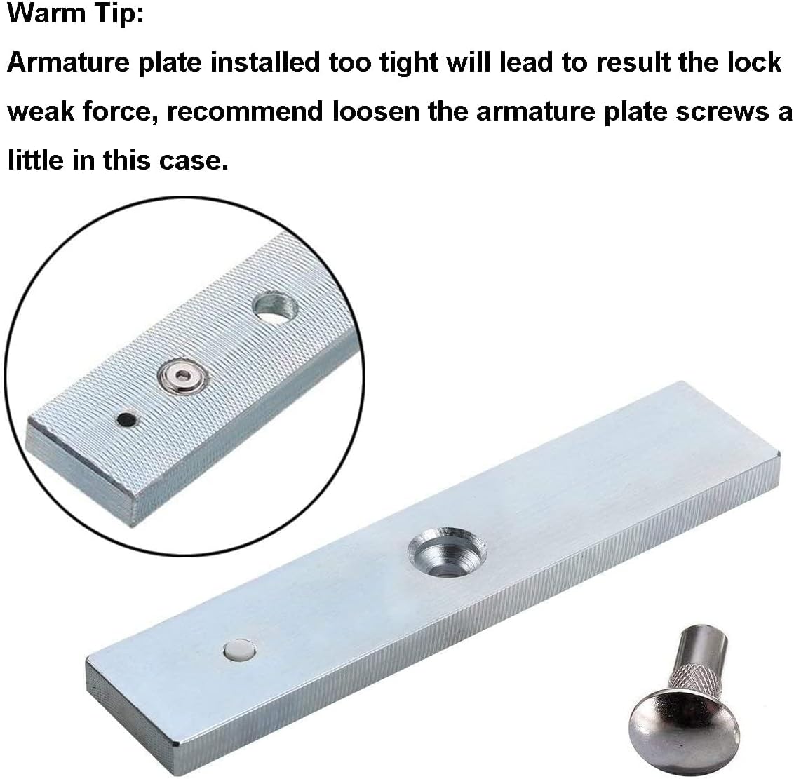
Figure 4: Close-up of the armature plate. It is crucial not to overtighten the armature plate screws. A slightly loose armature plate allows for better alignment with the electromagnet, ensuring maximum holding force.
6.3 Wiring
The electromagnetic lock requires connection to a 12VDC or 24VDC power supply and an access control system. Ensure the correct voltage is selected on the lock if applicable, or supplied by your power source.

Figure 5: Comprehensive wiring diagram illustrating connections between the electromagnetic lock, power supply, access control keypad, exit button, and door bell.

Figure 6: Internal view of the lock's circuit board, showing the terminal blocks for power input (V+, V-) and signal output (NO, NC, COM).
- Power Connection: Connect the positive (+) and negative (-) terminals of the lock to your 12VDC or 24VDC power supply. Ensure polarity is correct.
- Voltage Selection: If your lock has a voltage selection jumper, ensure it is set to match your power supply (12V or 24V).
- Access Control Integration: Connect the lock's control wires (typically to the NO/NC/COM terminals) to your access control system (e.g., keypad, card reader, exit button) as per the system's instructions. The lock operates in NC (Normally Closed) mode, meaning it locks when power is applied.
- Signal Output: The NO/NC/COM terminals can be used to provide lock status feedback to an access control panel or monitoring system.
- Test: After wiring, carefully test the lock's functionality with your access control system before finalizing the installation.
7. Operation
The UHPPOTE Double Door Electromagnetic Lock operates in a fail-safe (NC) mode. This means the lock is engaged (locked) when electrical power is supplied to it, and it disengages (unlocks) when the power is interrupted.
- Locking: When the access control system applies power to the electromagnetic lock, the electromagnet creates a magnetic field, attracting the armature plate and securing the door. The integrated LED will typically illuminate RED to indicate a locked state.
- Unlocking: When the access control system removes power (e.g., via an exit button, card swipe, or keypad entry), the magnetic field dissipates, allowing the door to be opened. The integrated LED will typically illuminate GREEN to indicate an unlocked state.
8. Maintenance
Regular maintenance ensures optimal performance and longevity of your electromagnetic lock.
- Cleaning: Keep the surfaces of both the electromagnet and the armature plate clean and free from dust, dirt, or debris. Use a soft, dry cloth. Do not use abrasive cleaners.
- Inspection: Periodically inspect all mounting screws and wiring connections to ensure they are secure. Tighten any loose screws.
- Alignment: Check the alignment between the electromagnet and the armature plate. Misalignment can reduce holding force.
- Cable Integrity: Ensure all cables are intact and free from damage. Replace any frayed or damaged wiring immediately.
9. Troubleshooting
Refer to the following common issues and solutions:
| Problem | Possible Cause | Solution |
|---|---|---|
| Lock has weak holding force or does not engage properly. | Armature plate screws are too tight, preventing proper alignment. Misalignment between electromagnet and armature plate. Dirt or debris on contact surfaces. Insufficient power supply. | Loosen the armature plate screws slightly to allow for minor movement and better alignment. Adjust the position of the lock or armature plate for optimal contact. Clean both surfaces thoroughly. Verify the power supply voltage and current meet specifications. |
| Lock does not engage (stay locked) when power is applied. | No power or incorrect voltage. Wiring error. Faulty lock unit. | Check power supply and ensure correct 12VDC or 24VDC is being delivered. Verify voltage selection jumper. Review wiring diagram and connections for errors. Contact support if power and wiring are confirmed correct. |
| Lock does not disengage (unlock) when power is removed. | Power is not being cut off. Stuck armature plate. | Check the access control system to ensure it is properly cutting power to the lock. Inspect the armature plate for any physical obstructions or damage. |
| LED indicator is not working or shows incorrect status. | Wiring issue to LED or bond sensor. Faulty LED/sensor. | Check internal wiring connections. Ensure the bond sensor is making proper contact. Contact support if issue persists. |
Important Tip: As mentioned in the product details, if the armature plate is installed too tightly, it can lead to weak locking force. It is recommended to loosen the armature plate screws slightly to allow for minor play and optimal contact with the electromagnet.
10. Support
For further assistance, technical support, or warranty inquiries, please contact UHPPOTE customer service through the retailer where the product was purchased or visit the official UHPPOTE website.
Please have your product model number (UT0531-280D) and purchase information ready when contacting support.