
1. Introduction
The Gikfun DIY SMD SMT Soldering Practice Board EK7028 is designed to enhance your surface mount device (SMD) and surface mount technology (SMT) soldering skills. This kit provides a practical platform for practicing soldering various component sizes, culminating in a functional blue LED water lamp circuit. It is suitable for hobbyists and students looking to improve their precision soldering techniques.

Figure 1: Gikfun DIY SMD SMT Soldering Practice Board EK7028
2. Safety Guidelines
Always prioritize safety when working with soldering equipment. Adhere to the following guidelines:
- Work in a well-ventilated area to avoid inhaling solder fumes.
- Wear appropriate eye protection (safety glasses) to shield against splashes or flying debris.
- Use a soldering iron stand to prevent accidental burns and keep the hot iron secure.
- Avoid touching the hot tip of the soldering iron or recently soldered components.
- Keep flammable materials away from your work area.
- Ensure proper disposal of solder waste and electronic components.
- Disconnect power to the soldering iron when not in use.
3. Package Contents
The Gikfun DIY SMD SMT Soldering Practice Board EK7028 kit includes the following items:

Figure 2: Contents of the Gikfun Soldering Practice Kit
Refer to the Bill of Materials for a detailed list of components:

Figure 3: Bill of Materials
| No. | SMD Package | Designator | Item Name | Qty |
|---|---|---|---|---|
| 1 | 1206 | R1-R12 | Resistor | 12 |
| 2 | 0805 | C1-C12 | Capacitor | 12 |
| 3 | 0805 | R13-R24 | Resistor | 12 |
| 4 | 0603 | R34-R47 | Resistor | 14 |
| 5 | 0603 | C13-C26 | Capacitor | 14 |
| 6 | 0402 | random | Resistor/Capacitor | 14 |
| 7 | 0805 | R50-R60, R65-R68 | Resistor (200-1K) | 15 |
| 8 | 0805 | D1-D11 | LED (Red/Blue) | 11 |
| 9 | 0805 | D16-D19 | LED (Emerald Green) | 4 |
| 10 | SOT23 | Q1-Q4 | Transistor (J3Y) | 4 |
| 11 | LL34 | D12-D15 | Diode (4148) | 4 |
| 12 | 0805 | R48, R61-R64 | Resistor (10K) | 5 |
| 13 | 0805 | R49 | Resistor (1M) | 1 |
| 14 | 0805 | C27, C28 | Capacitor (0.1uF) | 2 |
| 15 | SOP08 | U1 | IC (555) | 1 |
| 16 | SOP16 | U2 | IC (4017) | 1 |
4. Board Layout Overview
The practice board features clearly marked areas for different component sizes and a central circuit for the LED water lamp. The back of the board includes useful measurement tools and component footprint references.
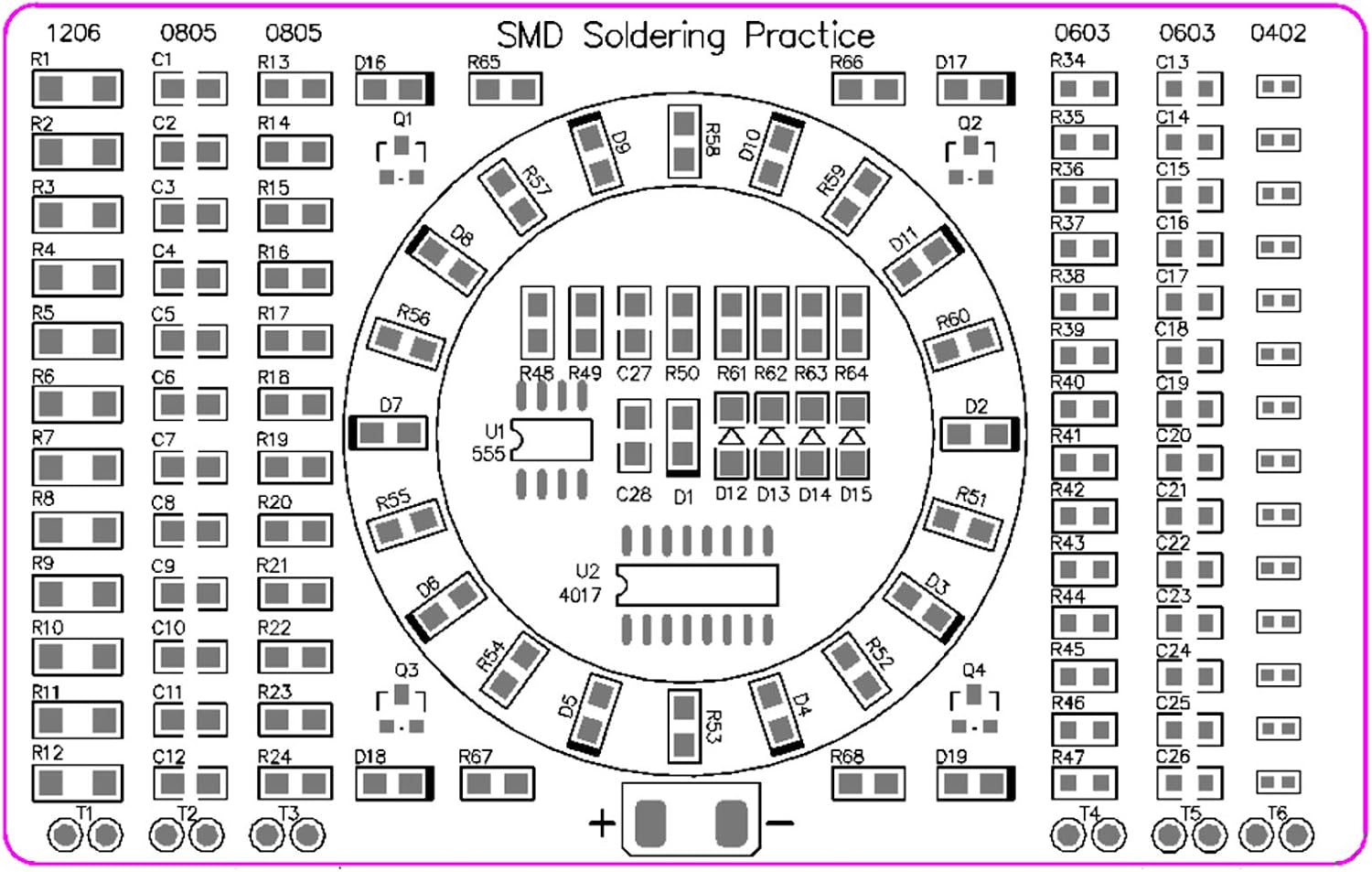
Figure 4: Front view of the practice board with component outlines

Figure 5: Back view of the practice board with measurement tools
5. Assembly Instructions
5.1. Preparation
- Gather necessary tools: fine-tip soldering iron, fine solder wire (e.g., 0.6mm diameter), flux pen or syringe, fine-point tweezers, multimeter, and magnification (e.g., USB microscope or headband magnifier).
- Organize components by size and type, referring to the Bill of Materials (Figure 3). Keep components in their tape strips until ready to solder to prevent loss.
- Ensure your workspace is clean, well-lit, and well-ventilated.
5.2. Soldering Practice Areas
The board is designed for progressive skill development, starting with larger components and moving to smaller ones. Begin with the largest components (1206) and proceed to 0805, 0603, and finally 0402. This allows you to gain confidence before tackling the smallest parts.
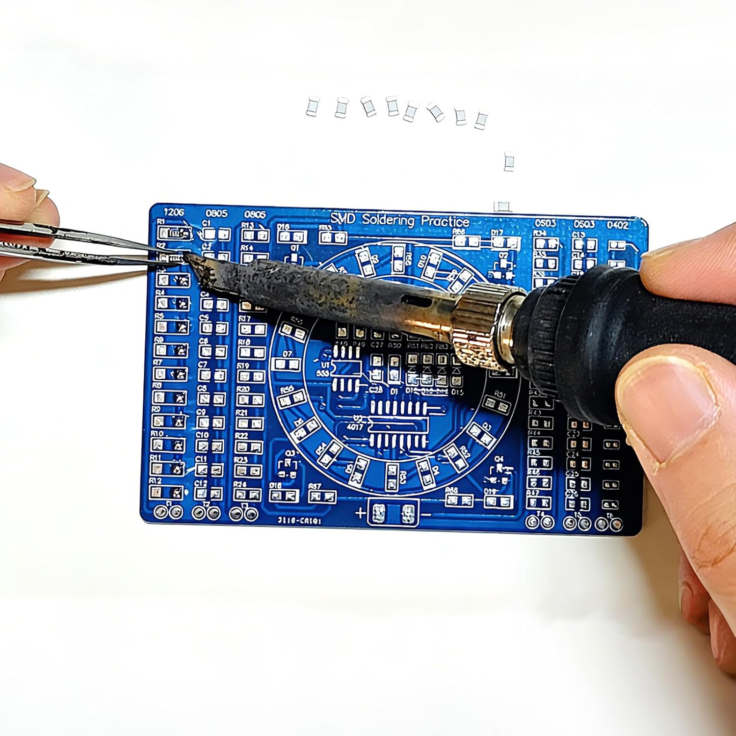
Figure 6: Soldering a component onto the board
- Apply Flux: Apply a small amount of flux to the solder pads where the component will be placed.
- Tin One Pad: Apply a small amount of solder to one of the pads for the component.
- Place Component: Using tweezers, carefully place the component onto the pads, aligning it correctly. Heat the tinned pad with your soldering iron and gently push the component into the molten solder. Remove the iron and hold the component in place until the solder solidifies.
- Solder Second Pad: Solder the opposite pad, ensuring a good connection. If necessary, re-heat the first pad and add more solder for a strong joint.
- Inspect: Visually inspect each solder joint for proper formation (shiny, smooth fillets). Use a multimeter to check for continuity if desired.
5.3. Main Circuit Assembly (LED Water Lamp)
After practicing on the side strips, proceed to assemble the central LED water lamp circuit. This circuit uses a NE555 timer (U1) and a CD4017 decade counter (U2) to create a sequential lighting effect.

Figure 7: Schematic Diagram of the LED Water Lamp Circuit
- Identify Components: Carefully identify each component for the central circuit using the Bill of Materials (Figure 3) and the board's silkscreen markings. Pay close attention to polarity for diodes (LEDs) and integrated circuits (ICs).
- Solder ICs (U1, U2): Solder the NE555 (U1) and CD4017 (U2) ICs first. Ensure correct orientation; the notch or dot on the IC should align with the marking on the PCB.
- Solder Resistors and Capacitors: Solder the remaining resistors (R48-R68) and capacitors (C27, C28) as indicated on the board.
- Solder Transistors (Q1-Q4): Solder the SOT23 transistors (Q1-Q4). Note their orientation.
- Solder Diodes (D12-D15): Solder the LL34 diodes (D12-D15). The band on the diode should match the band marking on the PCB.
- Solder LEDs (D1-D11, D16-D19): Solder the LEDs. The longer lead of the LED typically indicates the anode (+), and the shorter lead indicates the cathode (-). On the PCB, the square pad usually indicates the anode (+), and the round pad indicates the cathode (-). Verify with a multimeter in diode test mode if unsure.
6. Operating Instructions
Once all components are soldered, the board is ready for testing.
- Connect Power: Connect a DC power supply (3-12V) to the designated '+' and '-' terminals on the board. Ensure correct polarity.
- Observe LED Sequence: The blue LEDs in the central circuit should light up in a sequential