
1. Introduction
The UHPPOTE HBK-P01 Access Control Power Supply is designed to provide stable 12VDC power for various access control systems, including electric locks, intercoms, cameras, and doorbells. It features a wide input voltage range of 110-240VAC and a working current of 3A, ensuring reliable operation.
Key features include:
- Worldwide voltage input: 110 - 240VAC.
- Specifically designed for access control systems and intercom cameras.
- Provides 12VDC steady output voltage with 3A working current.
- Equipped with a rotary trimmer potentiometer for accurate delay time adjustment.
- Robust aluminum alloy enclosure with heat dissipation holes for optimal performance.
2. Safety Information
CAUTION: RISK OF ELECTRIC SHOCK. DO NOT OPEN.
- Ensure all power is disconnected before installation or maintenance.
- Installation should be performed by qualified personnel only.
- Do not expose the device to moisture or extreme temperatures.
- Ensure proper grounding to prevent electrical hazards.
- When connecting with an electric controlled lock, the opening time must be set to 0 seconds to prevent damage to the electric bolt lock.
3. Product Overview
The HBK-P01 power supply features a durable aluminum alloy enclosure designed for efficient heat dissipation, ensuring stable operation. It includes clearly labeled terminals for easy connection to various access control components.

Figure 3.1: UHPPOTE HBK-P01 Access Control Power Supply

Figure 3.2: Exploded view of the HBK-P01, highlighting its aluminum alloy enclosure and internal circuit board.
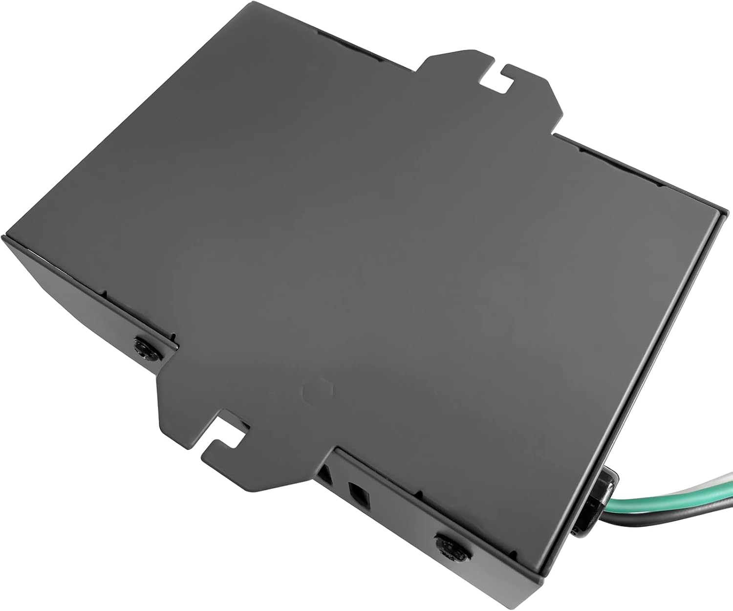
Figure 3.3: Heat dissipation holes on the HBK-P01 enclosure, designed to maintain optimal operating temperature.
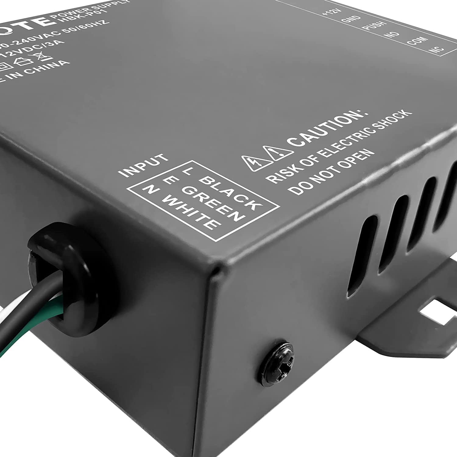
Figure 3.4: Rotary trimmer potentiometer for adjusting the delay time, offering precise control from 0 to 15 seconds.
3.1 Product Overview Video
Video 3.1: An animated overview of the HBK-P01 power supply, detailing its enclosure, heat dissipation features, and delay button functionality. This video also illustrates various wiring connections.
4. Setup and Installation
Follow these instructions carefully for proper installation and wiring of the HBK-P01 power supply with your access control system components.
4.1 Input Power Wiring
The power supply accepts an input voltage of 100-240VAC. Connect the input wires as follows:
- Connect the white wire to the neutral wire (N).
- Connect the green wire to the earth wire (E).
- Connect the black wire to the live wire (L).
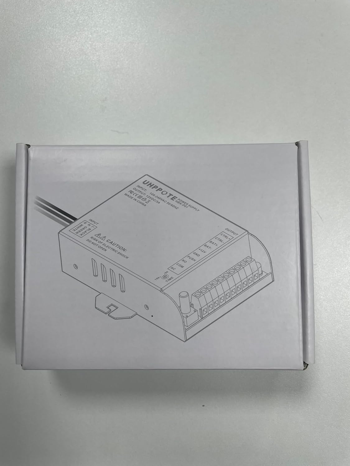
Figure 4.1: Input power wiring diagram, showing connections to Live (L), Neutral (N), and Earth (E) from a 110-240VAC source.
4.2 Component Wiring Overview
The following diagram illustrates the complete wiring for various access control components with the HBK-P01 power supply.

Figure 4.2: Comprehensive wiring diagram showing connections for access keypad, exit button, electric lock, intercom camera, and backup battery.
4.3 Detailed Wiring Instructions (Video)
For a step-by-step visual guide on connecting various components, please refer to the detailed wiring video below. Note that wiring for different access keypads may vary; always refer to the user manual of your specific access keypad.
Video 4.1: Detailed hands-on wiring instructions for the HBK-P01 power supply, covering connections for access keypads, exit buttons, fail-safe locks, and fail-secure locks.
4.3.1 Connecting an Access Keypad
- Connect the +12V terminal of the access keypad to the +12V terminal of the power supply.
- Connect the GND terminal of the access keypad to the GND terminal of the power supply.
- Connect the PUSH terminal of the access keypad to the PUSH terminal of the power supply.
4.3.2 Connecting an Exit Button
- Connect the NO (Normally Open) terminal of the exit button to the PUSH terminal of the power supply.
- Connect the COM (Common) terminal of the exit button to the GND terminal of the power supply.
4.3.3 Connecting an Electric Lock
The wiring depends on whether the lock is fail-safe or fail-secure:
- Fail-Safe Lock (Power to Lock): Connect the V+ of the lock to the NC (Normally Closed) terminal of the power supply. Connect the V- of the lock to the COM terminal of the power supply.
- Fail-Secure Lock (Power to Unlock): Connect the V+ of the lock to the NO (Normally Open) terminal of the power supply. Connect the V- of the lock to the COM terminal of the power supply.
Important: When connecting with an electric controlled lock, the opening time must be set to 0 seconds. Otherwise, the electric bolt lock may be damaged.
4.3.4 Connecting a Backup Battery
The HBK-P01 supports an external 12V backup battery for continuous operation during power outages.
- Connect the BAT+ terminal of the power supply to the positive pole (+) of the battery.
- Connect the BAT- terminal of the power supply to the negative pole (-) of the battery.
Remarks: We recommend a 12V 7Ah storage battery.
4.3.5 Connecting an Intercom Camera
The power supply can integrate with an intercom camera system.
- Use the CTRL+ and CTRL- terminals to connect with your intercom camera.
For specific wiring methods for your intercom camera, please refer to its user manual.
5. Operating Instructions
5.1 Delay Time Adjustment
The HBK-P01 features a rotary trimmer potentiometer for adjusting the output delay time. This allows you to control how long a connected electric lock remains unlocked after activation.
- Locate the TIME potentiometer on the power supply unit (refer to Figure 3.4).
- Use a small screwdriver to rotate the potentiometer. The delay time can be adjusted from 0 to 15 seconds.
- Adjust to your desired delay. Remember to set to 0 seconds for electric bolt locks to prevent damage.
6. Maintenance
To ensure the longevity and optimal performance of your UHPPOTE HBK-P01 Access Control Power Supply, follow these general maintenance guidelines:
- Keep the unit clean and free from dust and debris. Use a soft, dry cloth for cleaning.
- Ensure adequate ventilation around the unit to facilitate heat dissipation. Do not block the heat dissipation holes.
- Regularly check all wiring connections to ensure they are secure and free from corrosion.
- Avoid exposing the unit to direct sunlight, high humidity, or extreme temperatures.
- Do not attempt to open the enclosure or repair the unit yourself, as this may void the warranty and pose an electric shock risk.
7. Troubleshooting
If you encounter issues with your HBK-P01 power supply, consider the following basic troubleshooting steps:
- No Power Output: Check the input power connection (110-240VAC) and ensure the circuit breaker is on. Verify all wiring is correct and secure.
- Incorrect Lock Behavior: Double-check the wiring for your electric lock (fail-safe vs. fail-secure) and ensure it matches the lock type. Verify the delay time setting.
- Intermittent Operation: Inspect all connections for looseness or damage. Ensure the power supply is not overheating (check ventilation).
- Access Keypad/Exit Button Not Responding: Verify the keypad/button wiring to the power supply's PUSH and GND/COM terminals.
If the problem persists after performing these checks, please contact UHPPOTE customer support for further assistance.
8. Specifications
| Feature | Specification |
|---|---|
| Manufacturer | UHPPOTE |
| Part Number | UT0431-01 |
| Item Model Number | UT0431-01 |
| Input Voltage | 110-240VAC |
| Output Voltage | 12VDC |
| Working Current | 3A |
| Wattage | 36 watts |
| Maximum Power | 36 Watts |
| Item Weight | 7.3 ounces |
| Product Dimensions | 4.45 x 3.07 x 1.26 inches |
| Material | Aluminum |
| Color | Grey |
| Connector Type | Barrel Connector |
| Delay Time Adjustment | 0-15 seconds (via potentiometer) |
9. Warranty and Support
For warranty information, technical support, or any inquiries regarding your UHPPOTE HBK-P01 Access Control Power Supply, please contact UHPPOTE customer service through the retailer where the product was purchased or visit the official UHPPOTE website.
Please have your product model number (HBK-P01 or UT0431-01) and purchase details ready when contacting support.