1. Introduction
Thank you for choosing the Donner Wireless DMX512 System. This system provides a reliable and efficient wireless solution for DMX512 stage lighting control, eliminating the need for extensive DMX cabling. It is designed for professional stage, DJ, disco, party, and bar lighting applications. This manual will guide you through the setup, operation, and maintenance of your wireless DMX system.
The system includes one DMX512 wireless transmitter and seven DMX512 wireless receivers, operating on a 2.4G frequency band with automatic frequency hopping for stable signal transmission.
2. Safety Information
- Ensure the power adapters used are compatible with the device's voltage requirements.
- Do not expose the devices to rain, moisture, or extreme temperatures.
- Avoid placing the devices near strong electromagnetic fields, which may interfere with wireless signal transmission.
- Do not attempt to disassemble or modify the devices. Refer all servicing to qualified personnel.
- Keep the devices away from children.
- Only use the system with DMX512 compatible lighting equipment.
3. Package Contents
Please check the package to ensure all items are present and in good condition:
- 1 x Donner DMX512 Wireless Transmitter
- 7 x Donner DMX512 Wireless Receivers
- 8 x Power Adapters (Note: Devices require external power and do not have built-in batteries.)
4. Product Overview
The Donner Wireless DMX512 System consists of a transmitter and multiple receivers, designed for seamless wireless DMX signal transmission.

Image 4.1: Overview of the Donner Wireless DMX512 System components.
4.1. Component Identification
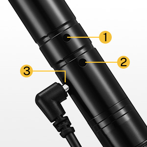
Image 4.2: Detailed view of a single DMX unit.
- Antenna: For wireless signal transmission and reception.
- DMX Connector: 3-pin XLR connector for DMX input (transmitter) or output (receiver).
- Power Input: DC 5V power jack for connecting the power adapter.
- ID Code Button/Indicator: Used to set the ID code and displays the current ID code via LED color.
4.2. Key Features
- Wireless DMX512 Protocol: Transmits standard DMX512 data wirelessly.
- 2.4G ISM Frequency Band: Operates in the 2.4GHz band, license-free worldwide.
- 126 Channels Automatic Frequency Hopping: Enhances anti-jamming capability and ensures reliable data transmission.
- 7 Group ID Codes: Allows multiple independent wireless networks in the same area without interference.
- Effective Communication Distance: Up to 500 meters (visible distance).
- No Time Delay: Ensures real-time DMX signal transmission.
5. Setup
5.1. Power Connection
Connect the provided power adapters to each transmitter and receiver unit. Plug the adapters into a standard AC power outlet. The units will power on automatically.
5.2. Setting ID Codes and Pairing
The wireless DMX system uses ID codes to establish independent wireless networks. For successful communication, the transmitter and all intended receivers must be set to the same ID code.
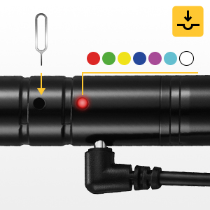
Image 5.1: ID Code Button and LED Indicator.
- Power On: Ensure all transmitter and receiver units are powered on.
- Select ID Code: Press the ID code button (often recessed, may require a small tool like a SIM ejector pin) on the transmitter. Each press will cycle through the 7 available ID codes, indicated by a different LED color.
- Match Receivers: For each receiver you wish to pair with this transmitter, press its ID code button until its LED color matches the transmitter's LED color.
- Confirmation: Once the ID codes match, the LED indicators on both the transmitter and receivers will flash rapidly, then settle into a slower, synchronized flash, indicating a successful connection.
ID Code Color Chart:
- 1: RED
- 2: GREEN
- 3: YELLOW
- 4: BLUE
- 5: PURPLE
- 6: CYAN
- 7: WHITE
5.3. Connection Diagram
The following diagrams illustrate typical connection scenarios for the wireless DMX system.

Image 5.2: Easy Connection - DMX console to transmitter, then wireless to receivers and lights.

Image 5.3: Advanced Connection - Utilizing multiple transmitters and receivers for complex setups.
- Connect the DMX output of your lighting console to the 3-pin XLR input of the wireless transmitter.
- Connect the 3-pin XLR output of each wireless receiver to the DMX input of your stage lighting fixtures.
- For multiple lights in a chain, connect the DMX output of the first light to the DMX input of the next, and so on.
6. Operating Instructions
6.1. Basic Operation
Once the transmitter and receivers are powered on and successfully paired with the same ID code:
- Ensure your DMX lighting console is sending DMX signals to the transmitter.
- The transmitter will convert the wired DMX signal into a wireless signal.
- The receivers will pick up the wireless signal and convert it back into a wired DMX signal for your lighting fixtures.
- Control your lights as usual from your DMX console. The wireless system acts as a transparent bridge for DMX data.
6.2. Multiple Wireless Networks
The 7 group ID codes allow you to create multiple independent wireless DMX networks in the same location without interference. This is useful for controlling different sets of lights or for complex stage setups.
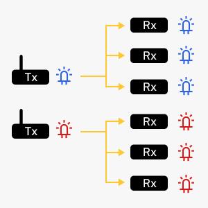
Image 6.1: Two independent wireless DMX networks (e.g., Blue ID and Red ID).
- To create a second network, use a separate transmitter and set it to a different ID code (e.g., GREEN).
- Pair the desired receivers with this second transmitter by setting them to the same GREEN ID code.
- Each network will operate independently, allowing for flexible control over various lighting zones.
7. Troubleshooting
- No Signal / Lights Not Responding:
- Ensure all units are powered on and their power adapters are securely connected.
- Verify that the transmitter and all receivers are set to the exact same ID code (matching LED color).
- Check DMX cable connections between the console and transmitter, and between receivers and lights.
- Confirm the DMX console is outputting a signal.
- Reduce the distance between the transmitter and receivers, or clear any obstructions.
- Intermittent Signal / Lag:
- Try changing the ID code to a different color to avoid potential interference from other 2.4G devices.
- Ensure the transmitter is receiving a strong, stable DMX signal from the console. A weak input signal can affect wireless performance.
- Check for physical obstructions or sources of electromagnetic interference.
- Ensure the units are within the effective communication range (up to 500m visible distance).
- LED Indicator Not Lighting Up:
- Check the power adapter and power outlet.
- Ensure the power cable is fully inserted into the unit's power input.
8. Specifications
| Feature | Specification |
|---|---|
| Model Number | US-EC803+EC804*7-DR-1 |
| Operating Frequency | 2.4G ISM band (2.400-2.525GHz) |
| Modulation Method | GFSK |
| DMX Channels | 512 |
| ID Codes | 7 groups (color-coded) |
| Communication Distance | Up to 500 meters (visible distance) |
| Sensitivity | -94dBm |
| Max Transmit Power | 20dBm |
| DMX Connector | 3-pin XLR male (transmitter), 3-pin XLR female (receiver) |
| Power Supply | DC 5V (via included power adapter) |
| Material | Metal |
| Dimensions (approx.) | 4.7 inches (11.9 cm) length, 3.5 inches (8.9 cm) antenna height |
| Item Weight (approx.) | 2.48 pounds (total package) |

Image 8.1: Approximate dimensions of a single DMX unit.
9. Maintenance
- Cleaning: Use a soft, dry cloth to clean the exterior of the units. Do not use abrasive cleaners or solvents.
- Storage: Store the devices in a cool, dry place away from direct sunlight and extreme temperatures when not in use.
- Cable Care: Regularly inspect power adapters and DMX cables for any signs of damage. Replace damaged cables immediately.
- Antenna: Ensure the antennas are securely attached and not bent or damaged.
10. Warranty and Support
Donner products are designed for reliability and performance. For warranty information, technical support, or service inquiries, please refer to the official Donner website or contact your authorized dealer. Please retain your proof of purchase for warranty claims.


