Tekpower YX-360TRe-b Analog Multimeter
User Manual
Model: YX-360TRe-b
1. Introduction
The Tekpower YX-360TR (also known as YX-360TReb and YX-360TRn) is a versatile analog multimeter designed for general purpose electrical testing. This device allows you to accurately measure AC/DC voltage, DC electric current, resistance, and perform diode and continuity checks. Its compact design, large mirrored scale, and built-in tilt stand make it a practical tool for various applications.
2. Safety Information
Always observe standard safety precautions when using any electrical testing equipment. Failure to do so may result in injury or damage to the meter or equipment under test.
- Read this manual thoroughly before operation.
- Ensure the test leads are in good condition, free from cracks or damage.
- Always select the correct function and range before connecting the test leads to the circuit.
- Never attempt to measure voltage on a current range setting, or vice versa.
- Do not use the meter if it appears damaged or if the case is open.
- Avoid using the meter in wet or damp conditions.
- Be cautious when working with voltages above 30V AC RMS, 42V peak, or 60V DC, as these pose a shock hazard.
- The meter is rated for CAT II installations, meaning it is suitable for measurements performed on circuits directly connected to the low-voltage installation.
3. Product Overview
The Tekpower YX-360TRe-b Analog Multimeter consists of several key components:
- Analog Display: Features a large, mirrored 80mm scale for precise readings across various measurement types.
- Rotary Function/Range Switch: Used to select the desired measurement function (DCV, ACV, DCA, Resistance, etc.) and the appropriate range.
- Input Jacks: Includes common (COM), voltage/resistance/mA (VΩmA), and 10A input terminals for connecting test leads.
- Zero Ohm Adjustment Knob: Used to zero the meter for resistance measurements.
- Tilt Back-Stand: Integrated stand for convenient viewing angle.
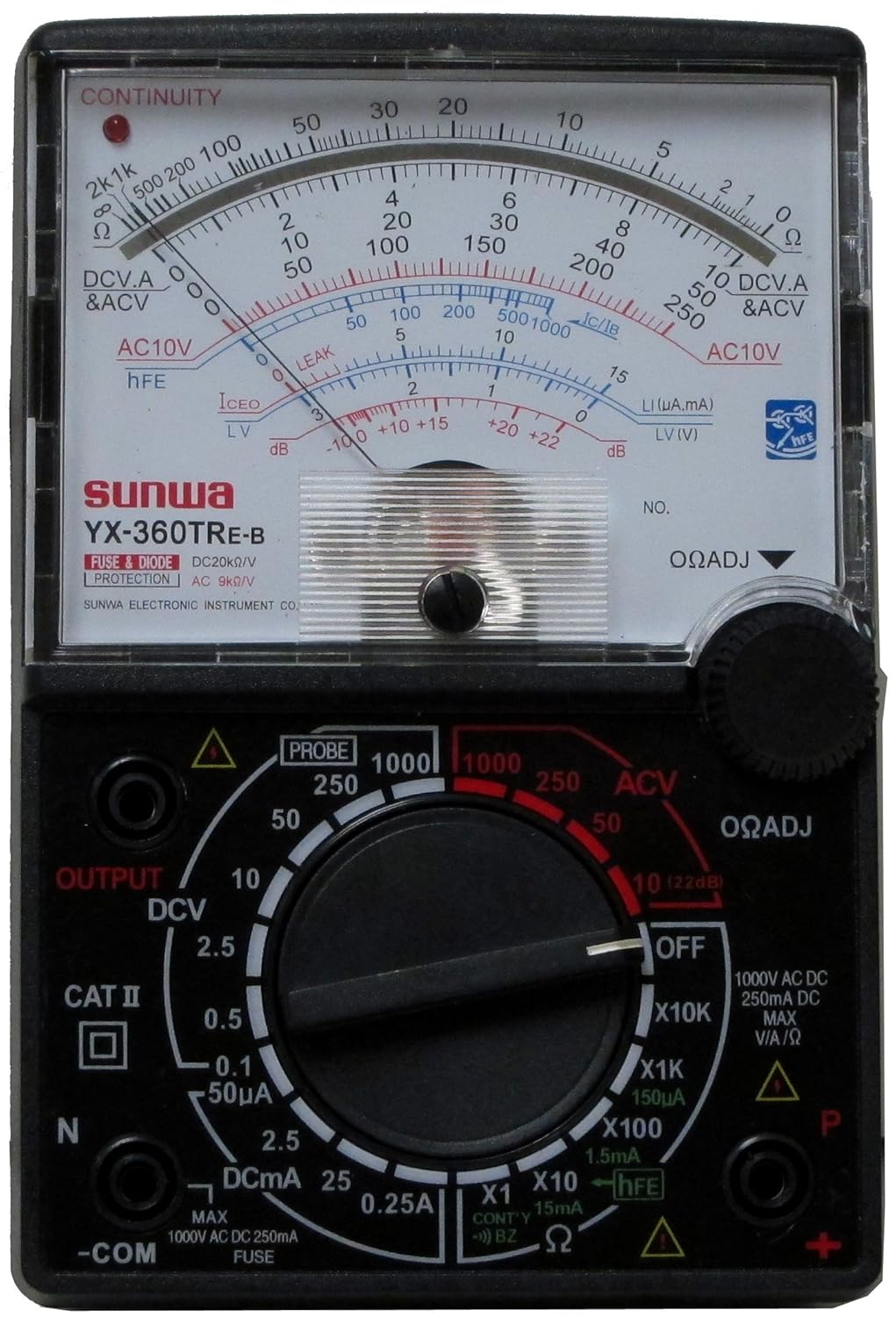
Figure 3.1: Front view of the Tekpower YX-360TRe-b Analog Multimeter, showing the analog display, rotary switch, and input jacks.
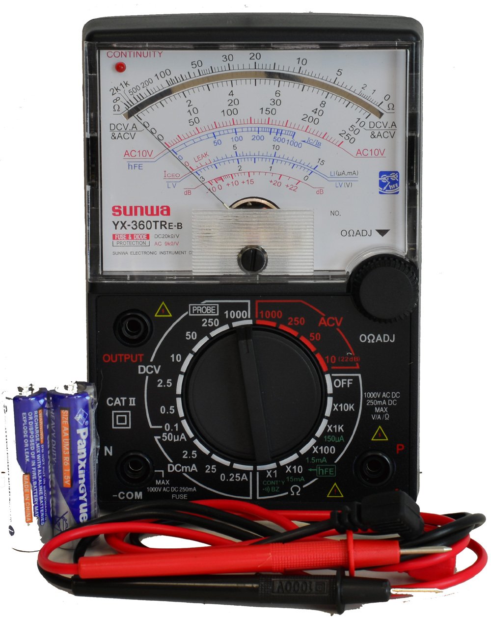
Figure 3.2: The Tekpower YX-360TRe-b Multimeter displayed with its included test leads and AA batteries.
4. Setup
4.1. Battery Installation
The Tekpower YX-360TRe-b requires two AA batteries for operation. These batteries are typically included with the multimeter.
- Locate the battery compartment cover on the back of the multimeter.
- Use a screwdriver to remove the screw(s) securing the cover, if present.
- Carefully open the battery compartment.
- Insert the two AA batteries, ensuring correct polarity (+ and -) as indicated inside the compartment.
- Replace the battery compartment cover and secure it with the screw(s).
4.2. Connecting Test Leads
Connect the red and black test leads to the appropriate input jacks on the multimeter.
- Insert the black test lead into the -COM (Common) jack. This is the negative terminal.
- Insert the red test lead into the VΩmA jack for most voltage, resistance, and current measurements (up to 250mA).
- For higher DC current measurements (up to 250mA), ensure the rotary switch is set to the appropriate DCA range.
5. Operating Instructions
Before taking any measurement, ensure the meter is set to the correct function and range. If the value is unknown, start with the highest range and work downwards.
5.1. DC Voltage (DCV) Measurement
- Set the rotary switch to the desired DCV range (e.g., 0.1V, 0.25V, 2.5V, 10V, 50V, 250V, 1000V).
- Connect the red test lead to the positive (+) side of the circuit and the black test lead to the negative (-) side.
- Read the voltage value from the DCV scale on the analog display.
5.2. AC Voltage (ACV) Measurement
- Set the rotary switch to the desired ACV range (e.g., 10V, 50V, 250V, 1000V).
- Connect the test leads across the AC voltage source.
- Read the voltage value from the ACV scale on the analog display.
5.3. DC Current (DCA) Measurement
- Important: Ensure the circuit is de-energized before connecting the meter in series.
- Set the rotary switch to the desired DCA range (e.g., 50µA, 2.5mA, 25mA, 250mA).
- Break the circuit and connect the multimeter in series with the load. The current must flow through the meter.
- Apply power to the circuit and read the current value from the DCA scale.
5.4. Resistance (Ω) Measurement
- Important: Ensure the circuit or component is de-energized before measuring resistance.
- Set the rotary switch to the desired Ω range (e.g., X1, X10, X100, X1K, X10K).
- Short the test leads together (touch the red and black probes).
- Adjust the ΩADJ (Zero Ohm Adjustment) knob until the needle points exactly to '0' on the Ohms scale.
- Connect the test leads across the component to be measured.
- Read the value from the Ohms scale and multiply by the range multiplier (e.g., if on X100 range and reading is 50, the resistance is 50 x 100 = 5000 Ω).
5.5. Diode Check
- Set the rotary switch to the Diode or Continuity function (often combined).
- Connect the red lead to the anode and the black lead to the cathode of the diode. The meter should show a low resistance reading.
- Reverse the leads. The meter should show a very high or infinite resistance reading.
- For LEDs, the LED should light up when connected in the forward bias direction.
5.6. Continuity Test
- Set the rotary switch to the Continuity function.
- Connect the test leads across the circuit or component to be tested.
- If there is continuity (low resistance), the meter will emit an audible buzzer sound and/or illuminate an LED indicator.
5.7. dB Measurement
The meter can measure decibels (dB) within a range of -10 dB to 22 dB. Refer to the specific dB scale on the analog display for readings.
6. Maintenance
6.1. Battery Replacement
When the meter's readings become erratic or the display dims, it's time to replace the batteries. Follow the steps in Section 4.1 for battery installation.
6.2. Fuse Replacement
The multimeter is equipped with fuse protection. If the meter stops functioning on current ranges, the fuse may need replacement. Refer to the meter's internal layout for fuse location and specifications. Always replace with a fuse of the same type and rating.
6.3. Cleaning and Storage
Wipe the meter's casing with a damp cloth and mild detergent. Do not use abrasives or solvents. Store the meter in a cool, dry place away from direct sunlight and extreme temperatures. If storing for extended periods, remove the batteries to prevent leakage.
7. Troubleshooting
| Problem | Possible Cause | Solution |
|---|---|---|
| No needle deflection / Meter not responding. | Dead or incorrectly installed batteries. Incorrect function/range selected. Blown fuse (for current measurements). Open circuit. | Check and replace batteries. Ensure correct polarity. Select appropriate function and range. Check and replace fuse if necessary. Verify circuit continuity. |
| Inaccurate readings. | Incorrect range selected. Poor contact with test leads. Battery low. Zero Ohm adjustment not performed (for resistance). | Select a more appropriate range. Ensure firm contact with test leads. Replace batteries. Perform Zero Ohm adjustment before resistance measurement. |
| Continuity buzzer not working. | Open circuit. Low battery. | Verify continuity of the circuit. Replace batteries. |
8. Specifications
| Parameter | Specification |
|---|---|
| Model | YX-360TRe-b (also YX-360TR, YX-360TReb, YX-360TRn) |
| DC Voltage (DCV) Ranges | 0.1V, 0.25V, 2.5V, 10V, 50V, 250V, 1000V |
| DCV Accuracy | ±1% (0.1V), ±3% (0.25V-1000V) |
| AC Voltage (ACV) Ranges | 10V, 50V, 250V, 1000V |
| ACV Accuracy | ±4% |
| DC Current (DCA) Ranges | 50µA, 2.5mA, 25mA, 250mA |
| DCA Accuracy | ±3% |
| Resistance Ranges | 2KΩ, 20KΩ, 200KΩ, 2MΩ, 20MΩ |
| Resistance Accuracy | ±3% |
| dB Range | -10 dB to 22 dB |
| Diode Check | Yes (including LED) |
| Continuity | Buzzer & LED indicator |
| DC/AC Sensitivity | 20kΩ/V |
| Battery Type | 2 x AA batteries (included) |
| Dimensions (L x W x H) | 7.7 x 3.6 x 2.2 inches |
| Net Weight | Approx. 12 ounces |
| Color | Black |
9. Warranty and Support
For information regarding the product warranty, please refer to the documentation included with your purchase or contact Tekpower directly. For technical support or inquiries, please visit the official Tekpower website or contact their customer service department.
Tekpower Store Link: Visit the Tekpower Store on Amazon


